Lexus NX: Installation
INSTALLATION
PROCEDURE
1. INSTALL BRAKE PEDAL PAD
(a) Install the brake pedal pad to the brake pedal support assembly.
2. INSTALL BRAKE PEDAL STROKE SENSOR ASSEMBLY
Click here .gif)
3. INSTALL BRAKE PEDAL SUPPORT ASSEMBLY
(a) Install the brake pedal support assembly with the 4 nuts.
Torque:
12.7 N·m {130 kgf·cm, 9 ft·lbf}
(b) Connect the 3 clamps to the brake pedal support assembly.
(c) Connect the connector to the brake pedal stroke sensor assembly.
(d) Install the brake pedal support reinforcement set bolt.
Torque:
23.6 N·m {241 kgf·cm, 17 ft·lbf}
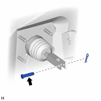
4. INSTALL PUSH ROD PIN
(a) Apply a light coat of lithium soap base glycol grease to the push rod pin.
(b) Set the push rod clevis in place, insert the push rod pin from inside the vehicle, and install a new clip.
.png) | Lithium soap base glycol grease |
NOTICE:
After installation, check that the pedal operates smoothly.
5. INSTALL BRAKE PEDAL RETURN SPRING
(a) Install the brake pedal return spring to the brake pedal support assembly and push rod pin.
6. INSTALL STOP LIGHT SWITCH ASSEMBLY
Click here
7. INSTALL UPPER INSTRUMENT PANEL SUB-ASSEMBLY
Click here
8. INSTALL LOWER NO. 1 INSTRUMENT PANEL AIRBAG ASSEMBLY
Click here
9. CONNECT CABLE TO NEGATIVE AUXILIARY BATTERY TERMINAL
(a) Connect the negative (-) auxiliary battery terminal and tighten the nut.
Torque:
5.4 N·m {55 kgf·cm, 48 in·lbf}
10. INITIALIZATION AFTER RECONECTING AUXILIARY BATTERY TERMINAL
Click here
HINT:
When disconnecting and reconnecting the auxiliary battery, there is an automatic learning function that completes learning when the respective system is used.
Click here
11. INSTALL DECK FLOOR BOX LH
Click here
12. INSTALL REAR DECK FLOOR BOX
Click here
13. INSTALL NO. 3 DECK BOARD SUB-ASSEMBLY
Click here
14. CHECK AND ADJUST BRAKE PEDAL
Click here
15. PERFORM INITIALIZATION AND CALIBRATION OF LINEAR SOLENOID VALVE
Click here
READ NEXT:
 Precaution
PRECAUTION CAUTION:
While the auxiliary battery is connected, even if the power switch is off, the brake control system activates when the brake pedal is depressed or the door courtesy switch is tu
Problem Symptoms Table
PROBLEM SYMPTOMS TABLE HINT: Use the table below to help determine the cause of problem symptoms. If multiple suspected areas are listed, the potential causes of the symptoms are listed in order of pr
SEE MORE:
Camera Position Adjustment Incomplete (C1697)
DESCRIPTION This DTC is stored when the parking assist ECU judges that the camera initial setting has not been memorized (camera view adjustment is incomplete). DTC No. Detection Item DTC Detection Condition Trouble Area C1697 Camera Position Adjustment Incomplete Camera initial set
Installation
INSTALLATION PROCEDURE 1. INSTALL RADIO RECEIVER ASSEMBLY 2. INSTALL NAVIGATION ECU Click here 3. INSTALL NO. 1 RADIO BRACKET (a) w/ Navigation System (1) Install the No. 1 radio bracket with the 5 screws. (b) w/o Navigation System (1) Install the No. 1 radio bracket with the 3 screws. 4. INSTALL
