Lexus NX: Installation
INSTALLATION
PROCEDURE
1. INSTALL NO. 3 MOTOR WATER JACKET COVER ASSEMBLY
(a) Remove any remaining seal packing from the transaxle housing installation surface and bolt holes.
NOTICE:
- Clean and degrease the installation surface and bolt holes.
- Do not allow any remaining seal packing to enter the coolant path when cleaning.
| (b) Apply seal packing in a continuous line as shown in the illustration. Seal Packing: Toyota Genuine Seal Packing 1282B, Three Bond 1282B or equivalent Standard Seal Diameter: 1.5 mm (0.0591 in.) or more. NOTICE: Remove any oil from the contact surface. |
|
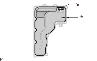
(c) Install a new No. 3 motor water jacket cover assembly to the hybrid vehicle transaxle with 12 new bolts.
Torque:
10 N·m {102 kgf·cm, 7 ft·lbf}
NOTICE:
- Install the No. 3 motor water jacket cover assembly within 3 minutes and tighten the bolts within 10 minutes after applying seal packing.
- Do not add coolant within 2 hours after installing the No. 3 motor water jacket cover assembly.
- Do not start the engine for at least 2 hours after installing the No. 3 motor water jacket cover assembly.
2. INSTALL NO. 1 MOTOR WATER JACKET COVER ASSEMBLY
(a) Remove any remaining seal packing from the transaxle housing installation surface and bolt holes.
NOTICE:
- Clean and degrease the installation surface and bolt holes.
- Do not allow any remaining seal packing to enter the coolant path when cleaning.
| (b) Apply seal packing in a continuous line as shown in the illustration. Seal Packing: Toyota Genuine Seal Packing 1282B, Three Bond 1282B or equivalent Standard Seal Diameter: 1.5 mm (0.0591 in.) or more. NOTICE: Remove any oil from the contact surface. |
|
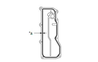
(c) Install a new No. 1 motor water jacket cover assembly to the hybrid vehicle transaxle with 8 new bolts.
Torque:
10 N·m {102 kgf·cm, 7 ft·lbf}
NOTICE:
- Install the No. 1 motor water jacket cover assembly within 3 minutes and tighten the bolts within 10 minutes after applying seal packing.
- Do not add coolant within 2 hours after installing the No. 1 motor water jacket cover assembly.
- Do not start the engine for at least 2 hours after installing the No. 1 motor water jacket cover assembly.
3. INSTALL NO. 2 AUTOMATIC TRANSMISSION CASE COVER
Click here .gif)
4. INSTALL OIL COOLER TUBE CLAMP
Click here
5. INSTALL NO. 1 TRANSMISSION CONTROL CABLE BRACKET
Click here
6. INSTALL FRONT ENGINE MOUNTING BRACKET
Click here
7. INSTALL HYBRID VEHICLE TRANSAXLE ASSEMBLY
Click here
8. INSTALL NO. 2 MOTOR WATER JACKET COVER ASSEMBLY
(a) Remove any remaining seal packing from the transaxle housing installation surface and bolt holes.
NOTICE:
- Clean and degrease the installation surface and bolt holes.
- Do not allow any remaining seal packing to enter the coolant path when cleaning.
| (b) Apply seal packing in a continuous line as shown in the illustration. Seal Packing: Toyota Genuine Seal Packing 1282B, Three Bond 1282B or equivalent Standard Seal Diameter: 1.5 mm (0.0591 in.) or more. NOTICE: Remove any oil from the contact surface. |
|
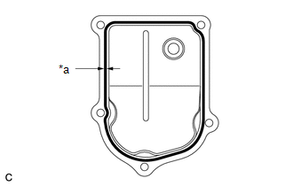
(c) Install a new No. 2 motor water jacket cover assembly to the hybrid vehicle transaxle with 5 new bolts.
Torque:
10 N·m {102 kgf·cm, 7 ft·lbf}
NOTICE:
- Install the No. 2 motor water jacket cover assembly within 3 minutes and tighten the bolts within 10 minutes after applying seal packing.
- Do not add coolant within 2 hours after installing the No. 2 motor water jacket cover assembly.
- Do not start the engine for at least 2 hours after installing the No. 2 motor water jacket cover assembly.
9. ADD COOLANT (for Inverter Coolant)
Click here
10. INSPECT FOR COOLANT LEAK (for Inverter Coolant)
Click here
11. INSTALL NO. 1 ENGINE UNDER COVER ASSEMBLY
Click here
READ NEXT:
 Components
COMPONENTS ILLUSTRATION *1 NO. 1 ENGINE UNDER COVER ASSEMBLY - - ILLUSTRATION *1 INVERTER BRACKET ASSEMBLY *2 INVERTER WATER PUMP WITH MOTOR ASSEMBLY *3 NO. 5 INVERTER COO
Removal
REMOVAL PROCEDURE 1. REMOVE NO. 1 ENGINE UNDER COVER ASSEMBLY Click here 2. REMOVE INVERTER WITH CONVERTER ASSEMBLY Click here 3. REMOVE INVERTER WATER PUMP WITH MOTOR ASSEMBLY Click here 4
SEE MORE:
Installation
INSTALLATION CAUTION / NOTICE / HINT HINT: A bolt without a torque specification is shown in the standard bolt chart. Click here PROCEDURE 1. INSTALL UPPER INSTRUMENT PANEL SUB-ASSEMBLY (a) Attach the 5 guides and 7 clips to install the upper instrument panel sub-assembly. (b) Install the 2 passen
Components
COMPONENTS ILLUSTRATION *A w/o Power Back Door System *B w/ Power Back Door System *1 BACK DOOR FINISH COVER LH *2 BACK DOOR FINISH COVER RH *3 BACK DOOR LOCK COVER *4 BACK DOOR OUTSIDE GARNISH SUB-ASSEMBLY *5 BACK DOOR SIDE GARNISH LH *6 BACK DOOR SIDE GARNIS
