- DTC judgment completed
- System normal
Lexus NX: Intake Air Temperature Circuit Low Input (P0112,P0113)
Lexus NX Service Manual / Engine & Hybrid System / 2ar-fxe (engine Control) / Sfi System / Intake Air Temperature Circuit Low Input (P0112,P0113)
DESCRIPTION
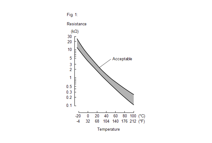
The intake air temperature sensor, mounted on the mass air flow meter sub-assembly, monitors the intake air temperature. The intake air temperature sensor has a built-in thermistor with a resistance that varies according to the temperature of the intake air. When the intake air temperature is low, the resistance of the thermistor increases. When the temperature is high, the resistance drops. These variations in resistance are transmitted to the ECM as voltage changes (see Fig. 1).
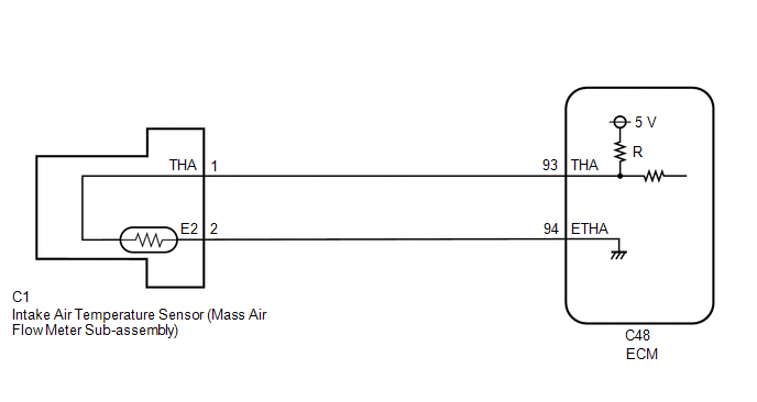
The intake air temperature sensor is powered by a 5 V supply from the THA terminal of the ECM, via resistor R.
Resistor R and the intake air temperature sensor are connected in series. When the resistance value of the intake air temperature sensor changes, according to changes in the intake air temperature, the voltage at terminal THA also varies. Based on this signal, the ECM increases the fuel injection volume when the engine is cold to improve driveability.
HINT:
When DTC P0112 or P0113 is stored, the ECM enters fail-safe mode. During fail-safe mode, the intake air temperature is estimated to be 20°C (68°F) by the ECM. Fail-safe mode continues until a pass condition is detected.
| DTC No. | Detection Item | DTC Detection Condition | Trouble Area | MIL | Memory |
|---|---|---|---|---|---|
| P0112 | Intake Air Temperature Circuit Low Input | A short in the intake air temperature sensor circuit for 0.5 seconds (1 trip detection logic). |
| Comes on | DTC stored |
| P0113 | Intake Air Temperature Circuit High Input | An open in the intake air temperature sensor circuit for 0.5 seconds (1 trip detection logic). |
| Comes on | DTC stored |
HINT:
When any of these DTCs are output, check the intake air temperature using the Techstream. Enter the following menus: Powertrain / Engine and ECT / Data List / Primary / Intake Air.
| Temperature Displayed | Malfunction |
|---|---|
| -40°C (-40°F) | Open circuit |
| Higher than 128°C (262°F) | Short circuit |
MONITOR DESCRIPTION
The ECM monitors the sensor voltage and uses this value to calculate the intake air temperature. When the sensor output voltage deviates from the normal operating range, the ECM interprets this as a malfunction in the intake air temperature sensor circuit and stores a DTC.
Example:
If the sensor output voltage is higher than 4.91 V for 0.5 seconds or more, the ECM determines that there is an open in the intake air temperature sensor circuit, and stores DTC P0113. Conversely, if the output voltage is less than 0.18 V for 0.5 seconds or more, the ECM determines that there is a short in the sensor circuit, and stores DTC P0112.
MONITOR STRATEGY
| Related DTCs | P0112: Intake air temperature sensor range check (low voltage) P0113: Intake air temperature sensor range check (high voltage) |
| Required Sensors/Components (Main) | Intake air temperature sensor |
| Required Sensors/Components (Related) | - |
| Frequency of Operation | Continuous |
| Duration | 0.5 seconds |
| MIL Operation | Immediate |
| Sequence of Operation | None |
TYPICAL ENABLING CONDITIONS
| Monitor runs whenever the following DTCs are not stored | None |
| Auxiliary battery voltage | 8 V or higher |
| Power switch | On (IG) |
TYPICAL MALFUNCTION THRESHOLDS
P0112| Intake air temperature sensor voltage [Intake air temperature] | Less than 0.18 V [Higher than 128°C (262°F)] |
| Intake air temperature sensor voltage [Intake air temperature] | Higher than 4.91 V [Less than -55°C (-67°F)] |
COMPONENT OPERATING RANGE
| Intake air temperature sensor voltage [Intake air temperature] | 0.18 to 4.91 V [-55 to 128°C (-67 to 262°F)] |
CONFIRMATION DRIVING PATTERN
- Connect the Techstream to the DLC3.
- Turn the power switch on (IG) and turn the Techstream on.
- Clear the DTCs (even if no DTCs are stored, perform the clear DTC procedure).
- Turn the power switch off and wait for at least 30 seconds.
- Turn the power switch on (IG) and turn the Techstream on.
- Wait 0.5 seconds or more.
- Enter the following menus: Powertrain / Engine and ECT / Trouble Codes.
-
Read the pending DTCs.
HINT:
- If a pending DTC is output, the system is malfunctioning.
- If a pending DTC is not output, perform the following procedure.
- Enter the following menus: Powertrain / Engine and ECT / Utility / All Readiness.
- Input the DTC: P0112 or P0113.
-
Check the DTC judgment result.
Techstream Display
Description
NORMAL
ABNORMAL
- DTC judgment completed
- System abnormal
INCOMPLETE
- DTC judgment not completed
- Perform driving pattern after confirming DTC enabling conditions
N/A
- Unable to perform DTC judgment
- Number of DTCs which do not fulfill DTC preconditions has reached ECU memory limit
HINT:
- If the judgment result shows NORMAL, the system is normal.
- If the judgment result shows ABNORMAL, the system has a malfunction.
-
If the judgment result is INCOMPLETE or N/A and no pending DTC is output, perform a universal trip and check for permanent DTCs.
Click here
.gif)
HINT:
- If a permanent DTC is output, the system is malfunctioning.
- If no permanent DTC is output, the system is normal.
WIRING DIAGRAM
CAUTION / NOTICE / HINT
HINT:
Read freeze frame data using the Techstream. The ECM records vehicle and driving condition information as freeze frame data the moment a DTC is stored. When troubleshooting, freeze frame data can help determine if the vehicle was moving or stationary, if the engine was warmed up or not, if the air fuel ratio was lean or rich, and other data from the time the malfunction occurred.
PROCEDURE
| 1. | READ VALUE USING TECHSTREAM (INTAKE AIR) |
(a) Connect the Techstream to the DLC3.
(b) Turn the power switch on (IG).
(c) Turn the Techstream on.
(d) Enter the following menus: Powertrain / Engine and ECT / Data List / Primary / Intake Air.
Powertrain > Engine and ECT > Data List| Tester Display |
|---|
| Intake Air |
(e) Read the value displayed on the Techstream.
OK:
Same as actual intake air temperature.
| Result | Proceed to |
|---|---|
| -40°C (-40°F) | A |
| Higher than 128°C (262°F) | B |
| Same as actual intake air temperature | C |
HINT:
- If there is an open circuit, the Techstream indicates -40°C (-40°F).
- If there is a short circuit, the Techstream indicates higher than 128°C (262°F).
| B | .gif) | GO TO STEP 4 |
| C | | CHECK FOR INTERMITTENT PROBLEMS |
|
.gif)
| 2. | READ VALUE USING TECHSTREAM (CHECK FOR OPEN IN WIRE HARNESS) |
| (a) Disconnect the mass air flow meter sub-assembly connector. |
|
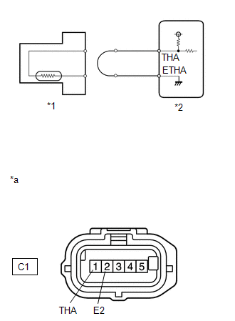
(b) Connect terminals C1-1 (THA) and C1-2 (E2) of the mass air flow meter sub-assembly connector on the wire harness side.
(c) Connect the Techstream to the DLC3.
(d) Turn the power switch on (IG).
(e) Turn the Techstream on.
(f) Enter the following menus: Powertrain / Engine and ECT / Data List / Primary / Intake Air.
Powertrain > Engine and ECT > Data List| Tester Display |
|---|
| Intake Air |
(g) Read the value displayed on the Techstream.
Standard value:
Higher than 128°C (262°F)
HINT:
Perform "Inspection After Repair" after replacing the mass air flow meter sub-assembly.
Click here
| OK | | REPLACE MASS AIR FLOW METER SUB-ASSEMBLY |
|
| 3. | CHECK HARNESS AND CONNECTOR (MASS AIR FLOW METER SUB-ASSEMBLY - ECM) |
(a) Disconnect the mass air flow meter sub-assembly connector.
(b) Disconnect the ECM connector.
(c) Measure the resistance according to the value(s) in the table below.
Standard Resistance:
| Tester Connection | Condition | Specified Condition |
|---|---|---|
| C1-1 (THA) - C48-93 (THA) | Always | Below 1 Ω |
| C1-2 (E2) - C48-94 (ETHA) | Always | Below 1 Ω |
| OK | | REPLACE ECM |
| NG | | REPAIR OR REPLACE HARNESS OR CONNECTOR |
| 4. | READ VALUE USING TECHSTREAM (CHECK FOR SHORT IN WIRE HARNESS) |
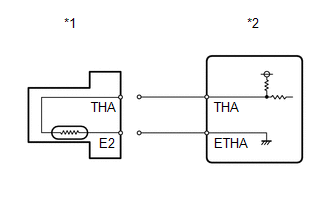
| *1 | Mass Air Flow Meter Sub-assembly |
| *2 | ECM |
(a) Disconnect the mass air flow meter sub-assembly connector.
(b) Connect the Techstream to the DLC3.
(c) Turn the power switch on (IG).
(d) Turn the Techstream on.
(e) Enter the following menus: Powertrain / Engine and ECT / Data List / Primary / Intake Air.
Powertrain > Engine and ECT > Data List| Tester Display |
|---|
| Intake Air |
(f) Read the value displayed on the Techstream.
Standard value:
-40°C (-40°F)
HINT:
Perform "Inspection After Repair" after replacing the mass air flow meter sub-assembly.
Click here
| OK | | REPLACE MASS AIR FLOW METER SUB-ASSEMBLY |
|
| 5. | CHECK HARNESS AND CONNECTOR (MASS AIR FLOW METER SUB-ASSEMBLY - ECM) |
(a) Disconnect the mass air flow meter sub-assembly connector.
(b) Disconnect the ECM connector.
(c) Measure the resistance according to the value(s) in the table below.
Standard Resistance:
| Tester Connection | Condition | Specified Condition |
|---|---|---|
| C1-1 (THA) or C48-93 (THA) - Body ground | Always | 10 kΩ or higher |
| OK | | REPLACE ECM |
| NG | | REPAIR OR REPLACE HARNESS OR CONNECTOR |
READ NEXT:
 Engine Coolant Temperature Circuit (P0115,P0117,P0118)
DESCRIPTION A thermistor, whose resistance value varies according to the engine coolant temperature, is built into the engine coolant temperature sensor. The structure of the sensor and its connection
Engine Coolant Temperature Circuit Range / Performance (P0116)
DESCRIPTION Refer to DTC P0115. Click here DTC No. Detection Item DTC Detection Condition Trouble Area MIL Memory P0116 Engine Coolant Temperature Circuit Range / Performance Ei
Engine Coolant Temperature / Intake Air Temperature Correlation (P011B)
DESCRIPTION The engine has two temperature sensors, an engine coolant temperature sensor and an intake air temperature sensor, to detect temperature while the engine is operating. A thermistor, whose
SEE MORE:
Vehicle Speed Signal Circuit between Stereo Component Amplifier and Combination Meter
DESCRIPTION The stereo component amplifier assembly receives a vehicle speed signal from the combination meter assembly to control the ASL function. HINT:
A voltage of 12 V or 5 V is output from each ECU and then input to the combination meter assembly. The signal is changed to a pulse signal at
Problem Symptoms Table
PROBLEM SYMPTOMS TABLE HINT:
Use the table below to help determine the cause of problem symptoms. If multiple suspected areas are listed, the potential causes of the symptoms are listed in order of probability in the "Suspected Area" column of the table. Check each symptom by checking the suspect
© 2016-2026 Copyright www.lexunx.com
