- If there is a malfunction due to the ACC relay being stuck on, the ACC relay does not turn off even though the power switch is off.
- If there is a malfunction due to the ACC relay being stuck off, the ACC relay does not turn on even though the power switch is on (ACC).
Lexus NX: ACC Monitor Malfunction (B2274)
Lexus NX Service Manual / Vehicle Interior / Theft Deterrent / Keyless Entry / Smart Access System With Push-button Start (for Start Function) / ACC Monitor Malfunction (B2274)
DESCRIPTION
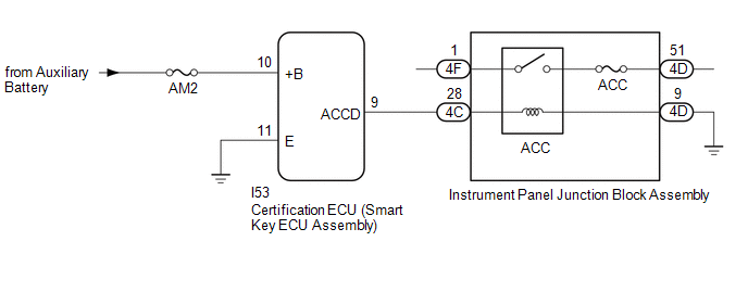
This DTC is stored when a malfunction in the ACC output circuit is detected. The ACC output circuit is the circuit that goes from the ACC output terminal of the certification ECU (smart key ECU assembly) to the ACC relay.
| DTC No. | Detection Item | DTC Detection Condition | Trouble Area | Note |
|---|---|---|---|---|
| B2274 | ACC Monitor Malfunction | Malfunction in the ACC relay circuit in the certification ECU (smart key ECU assembly) or in the external circuit (1-trip detection logic*). HINT: When the voltage at terminal ACCD is not at the standard, the system is determined to be malfunctioning. |
|
|
- *: Only detected while a malfunction is present.
| Vehicle Condition when Malfunction Detected | Fail-safe Function when Malfunction Detected |
|---|---|
| HINT: The power switch can be turned on (IG) and the hybrid control system can be started. | - |
| DTC No. | Data List and Active Test |
|---|---|
| B2274 | Power Source Control
|
WIRING DIAGRAM
CAUTION / NOTICE / HINT
NOTICE:
- When using the Techstream with the power switch off, connect the Techstream to the DLC3 and turn a courtesy light switch on and off at intervals of 1.5 seconds or less until communication between the Techstream and the vehicle begins. Then select the vehicle type under manual mode and enter the following menus: Body Electrical / Smart Access. While using the Techstream, periodically turn a courtesy light switch on and off at intervals of 1.5 seconds or less to maintain communication between the Techstream and the vehicle.
-
The smart access system with push-button start (for Start Function) uses the LIN communication system and CAN communication system. Inspect the communication function by following How to Proceed with Troubleshooting. Troubleshoot the smart access system with push-button start (for Start Function) after confirming that the communication systems are functioning properly.
Click here
.gif)
- Inspect the fuses of circuits related to this system before performing the following procedure.
-
Before replacing the certification ECU (smart key ECU assembly), refer to the smart access system with push-button start (for Start Function) Precaution.
Click here
- After repair, confirm that no DTCs are output by performing "DTC Output Confirmation Operation".
HINT:
When the cable is disconnected and reconnected to the negative (-) auxiliary battery terminal, the power source mode returns to the state it was in before the cable was disconnected.
PROCEDURE
| 1. | CHECK HARNESS AND CONNECTOR (POWER SOURCE) |
Click here
| NG | .gif) | REPAIR OR REPLACE HARNESS OR CONNECTOR IN CIRCUIT CONNECTED TO POWER SOURCE |
|
.gif)
| 2. | CHECK HARNESS AND CONNECTOR (GROUND) |
Click here
| NG | | REPAIR OR REPLACE HARNESS OR CONNECTOR |
|
| 3. | CHECK HARNESS AND CONNECTOR (CERTIFICATION ECU (SMART KEY ECU ASSEMBLY) - INSTRUMENT PANEL JUNCTION BLOCK ASSEMBLY) |
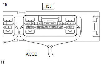
(a) Disconnect the I53 certification ECU (smart key ECU assembly) connector.
(b) Disconnect the 4C and 4D instrument panel junction block assembly connectors.
(c) Measure the resistance according to the value(s) in the table below.
Standard Resistance:
| Tester Connection | Condition | Specified Condition |
|---|---|---|
| I53-9 (ACCD) - 4C-28 | Always | Below 1 Ω |
| 4D-9 - Body ground | Always | Below 1 Ω |
| I53-9 (ACCD) or 4C-28 - Body ground | Always | 10 kΩ or higher |
| NG | | REPAIR OR REPLACE HARNESS OR CONNECTOR |
|
| 4. | CHECK INSTRUMENT PANEL JUNCTION BLOCK ASSEMBLY (ACC RELAY) |
(a) Remove the instrument panel junction block assembly.
Click here
(b) Measure the resistance according to the value(s) in the table below.
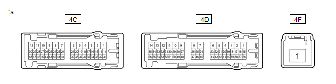
| *a | Component without harness connected (Instrument Panel Junction Block Assembly) | - | - |
Standard Resistance:
| Tester Connection | Condition | Specified Condition |
|---|---|---|
| 4C-28 - 4D-9 | 20°C (68°F) | 130.92 to 190.74 Ω |
| 4F-1 - 4D-51 | Auxiliary battery voltage not applied to terminals 4C-28 and 4D-9 | 10 kΩ or higher |
| Auxiliary battery voltage applied to terminals 4C-28 and 4D-9 | Below 1 Ω |
| NG | | REPLACE INSTRUMENT PANEL JUNCTION BLOCK ASSEMBLY |
|
| 5. | CHECK CERTIFICATION ECU (SMART KEY ECU ASSEMBLY) |
| (a) Reconnect the I53 certification ECU (smart key ECU assembly) connector. |
|
(b) Install the instrument panel junction block assembly.
Click here
(c) Measure the voltage according to the value(s) in the table below.
Standard Voltage:
| Tester Connection | Condition | Specified Condition |
|---|---|---|
| I53-9 (ACCD) - Body ground | Power switch off → Power switch on (ACC) | 1 V or less → 8.5 V or higher |
| OK | | END (TEMPORARY CONNECTION FAILURE IS SUSPECTED) |
| NG | | REPLACE CERTIFICATION ECU (SMART KEY ECU ASSEMBLY) |
READ NEXT:
 STSW Monitor Malfunction (B2275)
DESCRIPTION This DTC is stored when a malfunction is detected in the starter circuit inside the certification ECU (smart key ECU assembly). DTC No. Detection Item DTC Detection Condition Trou
Detecting Vehicle Submersion (B2277)
DESCRIPTION This DTC is stored when a malfunction in the water submersion detection circuit in the certification ECU (smart key ECU assembly) is detected. DTC No. Detection Item DTC Detection C
Vehicle Speed Signal Malfunction (B2282,B2283)
DESCRIPTION DTC B2282 is stored when the vehicle speed signal sent by the combination meter assembly via direct line and the vehicle speed signal sent via CAN communication do not match. DTC B2283 is
SEE MORE:
Software Incompatibility with Brake System Control Module Not Programmed (U031851)
DESCRIPTION If the forward recognition camera cannot verify the vehicle information sent from the skid control ECU (brake booster with master cylinder assembly), the forward recognition camera stores DTC U031851. DTC No. Detection Item DTC Detection Condition Trouble Area DTC Output from
Diagnostic Trouble Code Chart
DIAGNOSTIC TROUBLE CODE CHART Navigation System DTC No. Detection Item Link B1323 Lost Communication with Haptic Device B1324 Lost Communication with Meter B1325 Lost Communication with HUD B1326 Lost Communication with Clock Device (Local-CAN)
© 2016-2026 Copyright www.lexunx.com
