Lexus NX: Lost Communication with Blind Spot Monitor Slave Module (U0232)
DESCRIPTION
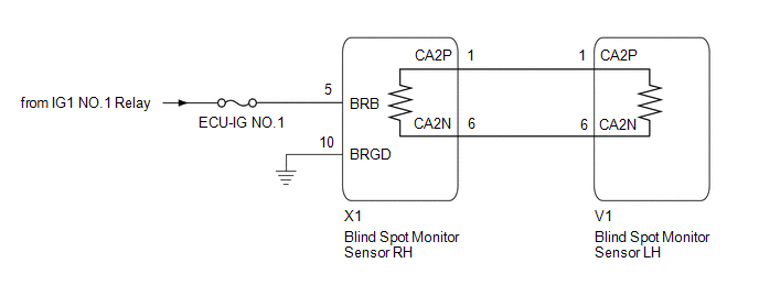
This DTC is stored when the blind spot monitor sensor LH judges that there is a communication error with the blind spot monitor sensor RH.
| DTC No. | Detection Item | DTC Detection Condition | Trouble Area | Note |
|---|---|---|---|---|
| U0232 | Lost Communication with Blind Spot Monitor Slave Module | The blind spot monitor sensor (master) cannot receive signals from the blind spot monitor sensor (slave) |
| - |
WIRING DIAGRAM
CAUTION / NOTICE / HINT
NOTICE:
- When checking for DTCs, make sure that the blind spot monitor main switch (multi-function switch) is on.
- Inspect the fuses for circuits related to this system before performing the following procedure.
- Before measuring the resistance of the CAN bus, turn the power switch off and leave the vehicle for 1 minute or more without operating the key or any switches, or opening or closing the doors. After that, disconnect the cable from the negative (-) auxiliary battery terminal and leave the vehicle for 1 minute or more before measuring the resistance.
-
After turning the power switch off, there may be a waiting time before disconnecting the negative (-) auxiliary battery terminal.
Click here
.gif)
-
When disconnecting and reconnecting the auxiliary battery terminal
Click here
HINT:
When disconnecting and reconnecting the auxiliary battery, there is an automatic learning function that completes learning when the respective system is used.
Click here
HINT:
- Operating the power switch, any other switches or a door triggers related ECU and sensor communication on the CAN. This communication will cause the resistance value to change.
- Even after DTCs are cleared, if a DTC is stored again after driving the vehicle for a while, the malfunction may be occurring due to vibration of the vehicle. In such a case, wiggling the ECUs or wire harness while performing the inspection below may help determine the cause of the malfunction.
PROCEDURE
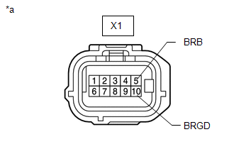
| 1. | CHECK HARNESS AND CONNECTOR (BLIND SPOT MONITOR SENSOR RH - BATTERY AND BODY GROUND) |
| (a) Disconnect the blind spot monitor sensor RH connector. |
|
(b) Measure the resistance according to the value(s) in the table below.
Standard Resistance:
| Tester Connection | Condition | Specified Condition |
|---|---|---|
| X1-10 (BRGD) - Body ground | Always | Below 1 Ω |
(c) Measure the voltage according to the value(s) in the table below.
Standard Voltage:
| Tester Connection | Switch Condition | Specified Condition |
|---|---|---|
| X1-5 (BRB) - Body ground | Power switch on (IG) | 11 to 14 V |
| X1-5 (BRB) - Body ground | Power switch off | Below 1 V |
| NG | .gif) | REPAIR OR REPLACE CAN LINE OR CONNECTOR |
|
.gif)
| 2. | CHECK FOR OPEN OR SHORT IN CAN BUS WIRES (BLIND SPOT MONITOR SENSOR LH) |
| (a) Disconnect the cable from the negative (-) auxiliary battery terminal. |
|
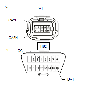
(b) Disconnect the blind spot monitor sensor LH connector.
(c) Measure the resistance according to the value(s) in the table below.
Standard Resistance:
| Tester Connection | Condition | Specified Condition |
|---|---|---|
| V1-1 (CA2P) - V1-6 (CA2N) | Cable disconnected from negative (-) auxiliary battery terminal | 108 to 132 Ω |
| V1-1 (CA2P) - I182-4 (CG) | Cable disconnected from negative (-) auxiliary battery terminal | 200 Ω or higher |
| V1-6 (CA2N) - I182-4 (CG) | Cable disconnected from negative (-) auxiliary battery terminal | 200 Ω or higher |
| V1-1 (CA2P) - I182-16 (BAT) | Cable disconnected from negative (-) auxiliary battery terminal | 6 kΩ or higher |
| V1-6 (CA2N) - I182-16 (BAT) | Cable disconnected from negative (-) auxiliary battery terminal | 6 kΩ or higher |
| OK | | REPLACE BLIND SPOT MONITOR SENSOR LH |
|
| 3. | CHECK FOR SHORT IN CAN BUS WIRES (BLIND SPOT MONITOR SENSOR RH) |
| (a) Disconnect the cable from the negative (-) auxiliary battery terminal. |
|

(b) Disconnect the blind spot monitor sensor RH connector.
(c) Measure the resistance according to the value(s) in the table below.
Standard Resistance:
| Tester Connection | Condition | Specified Condition |
|---|---|---|
| X1-1 (CA2P) - X1-6 (CA2N) | Cable disconnected from negative (-) auxiliary battery terminal | 108 to 132 Ω |
| X1-1 (CA2P) - I182-4 (CG) | Cable disconnected from negative (-) auxiliary battery terminal | 200 Ω or higher |
| X1-6 (CA2N) - I182-4 (CG) | Cable disconnected from negative (-) auxiliary battery terminal | 200 Ω or higher |
| X1-1 (CA2P) - I182-16 (BAT) | Cable disconnected from negative (-) auxiliary battery terminal | 6 kΩ or higher |
| X1-6 (CA2N) - I182-16 (BAT) | Cable disconnected from negative (-) auxiliary battery terminal | 6 kΩ or higher |
| OK | | REPLACE BLIND SPOT MONITOR SENSOR RH |
| NG | | REPAIR OR REPLACE CAN LINE OR CONNECTOR |
READ NEXT:
 Software Incompatibility with Body Control Module "B" (U1331)
DESCRIPTION This DTC is stored when the destination information of the main body ECU (multiplex network body ECU) does not match that of the blind spot monitor sensors. DTC No. Detection Item D
Main Switch Circuit
DESCRIPTION When the blind spot monitor main switch (combination switch assembly) is turned on, a signal is sent to the blind spot monitor sensor LH and the blind spot monitor indicator on the blind s
Power Source Circuit
DESCRIPTION This circuit provides power to operate the blind spot monitor sensor. WIRING DIAGRAM CAUTION / NOTICE / HINT NOTICE: Inspect the fuses for circuits related to this system before performin
SEE MORE:
Removal
REMOVAL PROCEDURE 1. REMOVE INSTRUMENT SIDE PANEL LH Click here 2. REMOVE NO. 1 INSTRUMENT PANEL SAFETY PAD SUB-ASSEMBLY Click here 3. REMOVE TRIP SWITCH (a) Using a screwdriver, detach the 2 claws and remove the trip switch. HINT: Tape the screwdriver tip before use. *1 Pr
Dtc Check / Clear
DTC CHECK / CLEAR CHECK DTC (a) Connect the Techstream to the DLC3. (b) Turn the power switch on (IG). (c) Turn the Techstream on. (d) Enter the following menus: Body Electrical / Front Radar Sensor / Trouble Codes. Body Electrical > Front Radar Sensor > Trouble Codes (e) Check for DTCs (Test
