Lexus NX: Main Switch Circuit
DESCRIPTION
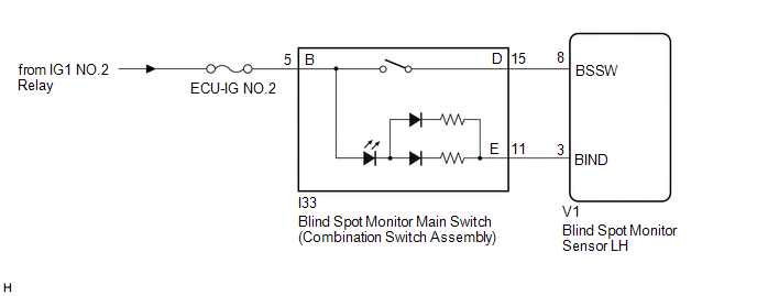
When the blind spot monitor main switch (combination switch assembly) is turned on, a signal is sent to the blind spot monitor sensor LH and the blind spot monitor indicator on the blind spot monitor main switch (combination switch assembly) illuminates. The blind spot monitor system operates according to this signal.
WIRING DIAGRAM
CAUTION / NOTICE / HINT
NOTICE:
Inspect the fuses for circuits related to this system before performing the following procedure.
PROCEDURE
| 1. | CHECK BLIND SPOT MONITOR MAIN SWITCH (COMBINATION SWITCH ASSEMBLY) |
(a) Check that the blind spot monitor indicator on the blind spot monitor main switch (combination switch assembly) illuminates normally when the blind spot monitor main switch (combination switch assembly) is turned from off to on.
(b) Check that the blind spot monitor indicator on the blind spot monitor main switch (combination switch assembly) turns off normally when the blind spot monitor main switch (combination switch assembly) is turned from on to off.
OK:
The blind spot monitor indicator operates normally.
| OK | .gif) | PROCEED TO NEXT SUSPECTED AREA SHOWN IN PROBLEM SYMPTOMS TABLE |
|
.gif)
| 2. | READ VALUE USING TECHSTREAM |
(a) Connect the Techstream to the DLC3.
(b) Turn the power switch on (IG).
(c) Turn the Techstream on.
(d) Enter the following menus: Body Electrical / Blind Spot Monitor Master / Data List.
(e) According to the display on Techstream, read the Data List.
Click here .gif)
| Tester Display | Measurement Item | Range | Normal Condition | Diagnostic Note |
|---|---|---|---|---|
| Main Switch | State of the blind spot monitor main switch (combination switch assembly) | OFF or ON | OFF: Blind spot monitor main switch (combination switch assembly) off ON: Blind spot monitor main switch (combination switch assembly) on | - |
| Main Switch Indicator Status | State of the blind spot monitor indicator on the blind spot monitor main switch (combination switch assembly) | OFF or ON | OFF: Indicator not illuminated ON: Indicator illuminated | - |
| Tester Display |
|---|
| Main Switch |
| Main Switch Indicator Status |
| Result | Proceed to |
|---|---|
| The status of "Main Switch" and "Main Switch Indicator Status" change as shown above when the blind spot monitor main switch (combination switch assembly) is operated. | A |
| The status of "Main Switch" does not change as shown above when the blind spot monitor main switch (combination switch assembly) is operated. | B |
| The status of "Main Switch Indicator Status" changes as shown above when the blind spot monitor main switch (combination switch assembly) is operated. | C |
| A | | REPLACE BLIND SPOT MONITOR MAIN SWITCH (COMBINATION SWITCH ASSEMBLY) |
| C | | GO TO STEP 6 |
|
| 3. | CHECK HARNESS AND CONNECTOR (COMBINATION SWITCH ASSEMBLY - BATTERY) |
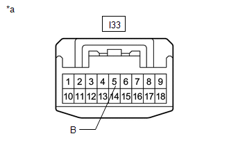
| (a) Disconnect the blind spot monitor main switch (combination switch assembly) connector. |
|
(b) Measure the voltage according to the value(s) in the table below.
Standard Voltage:
| Tester Connection | Switch Condition | Specified Condition |
|---|---|---|
| I33-5 (B) - Body ground | Power switch on (IG) | 11 to 14 V |
| I33-5 (B) - Body ground | Power switch off | Below 1 V |
| NG | | REPAIR OR REPLACE HARNESS OR CONNECTOR |
|
| 4. | INSPECT BLIND SPOT MONITOR MAIN SWITCH (COMBINATION SWITCH ASSEMBLY) |
(a) Remove the blind spot monitor main switch (combination switch assembly).
Click here
(b) Inspect the blind spot monitor main switch (combination switch assembly).
Click here
| NG | | REPLACE BLIND SPOT MONITOR MAIN SWITCH (COMBINATION SWITCH ASSEMBLY) |
|
| 5. | CHECK HARNESS AND CONNECTOR (BLIND SPOT MONITOR MAIN SWITCH [COMBINATION SWITCH ASSEMBLY] - BLIND SPOT MONITOR SENSOR LH) |
(a) Disconnect the V1 blind spot monitor sensor LH connector.
(b) Disconnect the I33 blind spot monitor main switch (combination switch assembly) connector.
(c) Measure the resistance according to the value(s) in the table below.
Standard Resistance:
| Tester Connection | Condition | Specified Condition |
|---|---|---|
| V1-8 (BSSW) - I33-15 (D) | Always | Below 1 Ω |
| V1-8 (BSSW) - Body ground | Always | 10 kΩ or higher |
| OK | | REPLACE BLIND SPOT MONITOR SENSOR LH |
| NG | | REPAIR OR REPLACE HARNESS OR CONNECTOR |
| 6. | INSPECT BLIND SPOT MONITOR MAIN SWITCH (COMBINATION SWITCH ASSEMBLY) |
(a) Remove the blind spot monitor main switch (combination switch assembly).
Click here
(b) Inspect the blind spot monitor main switch (combination switch assembly).
Click here
| NG | | REPLACE BLIND SPOT MONITOR MAIN SWITCH (COMBINATION SWITCH ASSEMBLY) |
|
| 7. | CHECK HARNESS AND CONNECTOR (BLIND SPOT MONITOR MAIN SWITCH [COMBINATION SWITCH ASSEMBLY] - BLIND SPOT MONITOR SENSOR LH) |
(a) Disconnect the V1 blind spot monitor sensor LH connector.
(b) Disconnect the I33 blind spot monitor main switch (combination switch assembly) connector.
(c) Measure the resistance according to the value(s) in the table below.
Standard Resistance:
| Tester Connection | Condition | Specified Condition |
|---|---|---|
| V1-3 (BIND) - I33-11 (E) | Always | Below 1 Ω |
| V1-3 (BIND) - Body ground | Always | 10 kΩ or higher |
| OK | | REPLACE BLIND SPOT MONITOR SENSOR LH |
| NG | | REPAIR OR REPLACE HARNESS OR CONNECTOR |
READ NEXT:
 Power Source Circuit
DESCRIPTION This circuit provides power to operate the blind spot monitor sensor. WIRING DIAGRAM CAUTION / NOTICE / HINT NOTICE: Inspect the fuses for circuits related to this system before performin
Clearance Warning Buzzer (for Front Side)
ComponentsCOMPONENTS ILLUSTRATION *1 NO. 1 CLEARANCE WARNING BUZZER - -
Clearance Warning Buzzer (for Rear Side)
ComponentsCOMPONENTS ILLUSTRATION *1 CLEARANCE WARNING BUZZER NO. 2 *2 TONNEAU COVER ASSEMBLY *3 UPPER DECK TRIM SIDE BOARD RH - - RemovalREMOVAL PROCEDURE 1. REMOVE TONNEAU C
SEE MORE:
Removal
REMOVAL PROCEDURE 1. REMOVE ENGINE OIL LEVEL DIPSTICK GUIDE (a) Remove the engine oil level dipstick. (b) Remove the bolt and engine oil level dipstick guide. (c) Remove the O-ring from the engine oil level dipstick guide. 2. REMOVE V-RIBBED BELT TENSIONER ASSEMBLY (a) Remove the b
Screen Flicker or Color Distortion
PROCEDURE 1. CHECK DISPLAY SETTING (a) Reset display settings (contrast, brightness) and check that the screen appears normal. OK: The display returns to normal. OK END (DISPLAY SETTING WAS CAUSE OF MALFUNCTION) NG PROCEED TO NEXT SUSPECTED AREA SHOWN IN PROBLEM SYMPTOMS TA
