Lexus NX: Power Source Circuit
DESCRIPTION
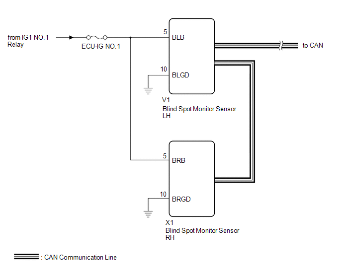
This circuit provides power to operate the blind spot monitor sensor.
WIRING DIAGRAM
CAUTION / NOTICE / HINT
NOTICE:
Inspect the fuses for circuits related to this system before performing the following inspection procedure.
PROCEDURE
| 1. | CHECK HARNESS AND CONNECTOR (BLIND SPOT MONITOR SENSOR LH, BLIND SPOT MONITOR SENSOR RH - BATTERY AND BODY GROUND) |
| (a) Disconnect the blind spot monitor sensor LH connector. |
|
(b) Disconnect the blind spot monitor sensor RH connector.
(c) Measure the voltage according to the value(s) in the table below.
Standard Voltage:
| Tester Connection | Switch Condition | Specified Condition |
|---|---|---|
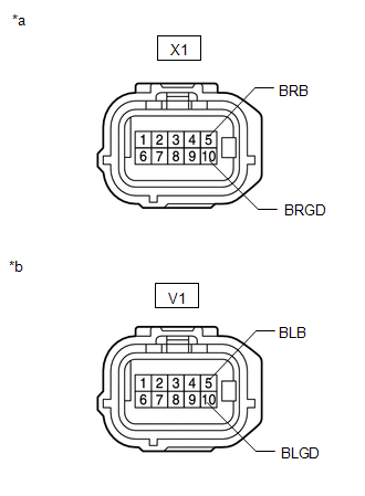
| V1-5 (BLB) - Body ground | Power switch on (IG) | 11 to 14 V |
| V1-5 (BLB) - Body ground | Power switch off | Below 1 V |
| X1-5 (BRB) - Body ground | Power switch on (IG) | 11 to 14 V |
| X1-5 (BRB) - Body ground | Power switch off | Below 1 V |
(d) Measure the resistance according to the value(s) in the table below.
Standard Resistance:
| Tester Connection | Condition | Specified Condition |
|---|---|---|
| V1-10 (BLGD) - Body ground | Always | Below 1 Ω |
| X1-10 (BRGD) - Body ground | Always | Below 1 Ω |
| OK | .gif) | PROCEED TO NEXT SUSPECTED AREA SHOWN IN PROBLEM SYMPTOMS TABLE |
.gif)
| NG | | REPAIR OR REPLACE HARNESS OR CONNECTOR |
READ NEXT:
 Clearance Warning Buzzer (for Front Side)
ComponentsCOMPONENTS ILLUSTRATION *1 NO. 1 CLEARANCE WARNING BUZZER - -
Clearance Warning Buzzer (for Rear Side)
ComponentsCOMPONENTS ILLUSTRATION *1 CLEARANCE WARNING BUZZER NO. 2 *2 TONNEAU COVER ASSEMBLY *3 UPPER DECK TRIM SIDE BOARD RH - - RemovalREMOVAL PROCEDURE 1. REMOVE TONNEAU C
SEE MORE:
Precaution
PRECAUTION NOTICE: When disassembling the rear combination light assembly, use static electricity countermeasures SST (desktop antistatic mat set) and observe all precautions to prevent damage to the system by electrostatic discharge (ESD). STATIC ELECTRICITY COUNTERMEASURES SST SST:Desktop antistat
Slide Sensor Malfunction (B2650)
DESCRIPTION When the front power seat switch LH does not receive a sensor signal despite forward or backward movement of the seat by power seat motor operation, this DTC is stored. DTC No. Detection Item DTC Detection Condition Trouble Area B2650 Slide Sensor Malfunction The forward
