Lexus NX: Lost Communication with Haptic Device (B1323-B1326)
DESCRIPTION
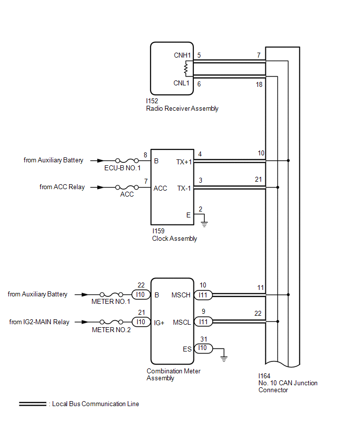
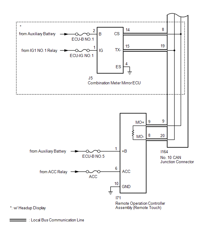
These DTCs are stored when communication between the radio receiver assembly and remote operation controller assembly (remote touch), combination meter assembly, combination meter mirror ECU* or clock assembly is not possible.
- *: w/ Headup Display
| DTC No. | Detection Item | DTC Detection Condition | Trouble Area |
|---|---|---|---|
| B1323 | Lost Communication with Haptic Device | CAN reception error |
|
| B1324 | Lost Communication with Meter | CAN reception error |
|
| B1325 | Lost Communication with HUD | CAN reception error |
|
| B1326 | Lost Communication with Clock Device (Local-CAN) | CAN reception error |
|
HINT:
The radio receiver assembly is the master unit.
WIRING DIAGRAM
CAUTION / NOTICE / HINT
NOTICE:
-
When replacing the radio receiver assembly, always replace it with a new one.
If a radio receiver assembly which was installed to another vehicle is used, the following may occur:
- A communication malfunction DTC may be stored.
- The radio receiver assembly may not operate normally.
-
After turning the power switch off, waiting time may be required before disconnecting the cable from the negative (-) auxiliary battery terminal.
Click here
.gif)
-
When disconnecting and reconnecting the auxiliary battery.
Click here
- Inspect the fuses for circuits related to this system before performing the following procedure.
HINT:
- B1323, B1324, B1325 and B1326 will not continue to output when clear DTC is performed even if the malfunction continues.
-
Depending on the parts that are replaced during vehicle inspection or maintenance, performing initialization, registration or calibration may be needed. Refer to Precaution for Audio and Visual System.
Click here
-
When disconnecting and reconnecting the auxiliary battery, there is an automatic learning function that completes learning when the respective system is used.
Click here
PROCEDURE
| 1. | CHECK DTC |
(a) Check for DTCs.
Click here
| Result | Proceed to |
|---|---|
| DTCs B1323, B1324, B1325* and B1326 are output | A |
| DTC B1323 is output | B |
| DTC B1324 is output | C |
| DTCs B1325 is output* | D |
| DTC B1326 is output | E |
| B | .gif) | GO TO STEP 3 |
| C | | GO TO STEP 16 |
| D | | GO TO STEP 20 |
| E | | GO TO STEP 24 |
|
.gif)
| 2. | CHECK LOCAL BUS |
| (a) Disconnect the cable from the negative (-) auxiliary battery terminal. |
|
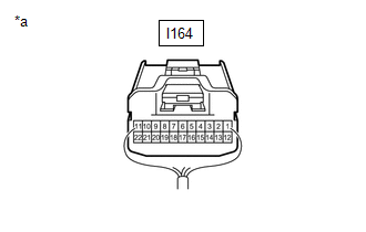
(b) Measure the resistance according to the value(s) in the table below.
Standard Resistance:
| Tester Connection | Condition | Specified Condition |
|---|---|---|
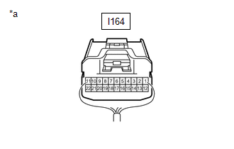
| I164-7 - I164-18 | Cable disconnected from negative (-) auxiliary battery terminal | 54 to 69 Ω |
| Result | Proceed to |
|---|---|
| OK | A |
| NG (Below 54 Ω) | B |
| NG (70 Ω or higher) | C |
| A | | USE SIMULATION METHOD TO CHECK |
| B | | GO TO STEP 5 |
| C | | GO TO STEP 18 |
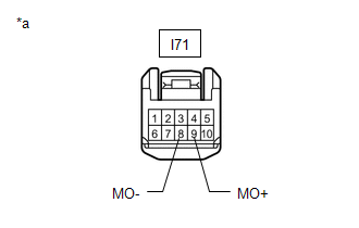
| 3. | CHECK HARNESS AND CONNECTOR (REMOTE OPERATION CONTROLLER ASSEMBLY [REMOTE TOUCH] POWER SOURCE) |
| (a) Disconnect the remote operation controller assembly (remote touch) connector. |
|
(b) Measure the resistance according to the value(s) in the table below.
Standard Resistance:
| Tester Connection | Condition | Specified Condition |
|---|---|---|
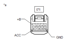
| I71-10 (GND) - Body ground | Always | Below 1 Ω |
(c) Measure the voltage according to the value(s) in the table below.
Standard Voltage:
| Tester Connection | Condition | Specified Condition |
|---|---|---|
| I71-1 (+B) - Body ground | Power switch off | 11 to 14 V |
| I71-6 (ACC) - Body ground | Power switch on (ACC) | 11 to 14 V |
| NG | | REPAIR OR REPLACE HARNESS OR CONNECTOR |
|
| 4. | CHECK HARNESS AND CONNECTOR (REMOTE OPERATION CONTROLLER ASSEMBLY [REMOTE TOUCH] - NO. 10 CAN JUNCTION CONNECTOR) |
| (a) Disconnect the cable from the negative (-) auxiliary battery terminal. |
|

(b) Disconnect the remote operation controller assembly (remote touch) connector.
(c) Measure the resistance according to the value(s) in the table below.
Standard Resistance:
| Tester Connection | Condition | Specified Condition |
|---|---|---|
| I71-9 (MO+) - I71-8 (MO-) | Cable disconnected from negative (-) auxiliary battery terminal | 108 to 132 Ω |
| OK | | REPLACE REMOTE OPERATION CONTROLLER ASSEMBLY (REMOTE TOUCH) |
| NG | | REPAIR OR REPLACE HARNESS OR CONNECTOR |
| 5. | CHECK HARNESS AND CONNECTOR (NO. 10 CAN JUNCTION CONNECTOR - RADIO RECEIVER ASSEMBLY) |
(a) Disconnect the No. 10 CAN junction connector.
| (b) Measure the resistance according to the value(s) in the table below. Standard Resistance:
|
|
| NG | | GO TO STEP 11 |
|
| 6. | CHECK HARNESS AND CONNECTOR (NO. 10 CAN JUNCTION CONNECTOR - REMOTE OPERATION CONTROLLER ASSEMBLY [REMOTE TOUCH]) |
| (a) Disconnect the No. 10 CAN junction connector. |
|

(b) Measure the resistance according to the value(s) in the table below.
Standard Resistance:
| Tester Connection | Condition | Specified Condition |
|---|---|---|
| I164-9 - I164-20 | Cable disconnected from negative (-) auxiliary battery terminal | 108 to 132 Ω |
| NG | | GO TO STEP 12 |
|
| 7. | CHECK HARNESS AND CONNECTOR (NO. 10 CAN JUNCTION CONNECTOR - COMBINATION METER ASSEMBLY) |
| (a) Disconnect the No. 10 CAN junction connector. |
|

(b) Measure the resistance according to the value(s) in the table below.
Standard Resistance:
| Tester Connection | Condition | Specified Condition |
|---|---|---|
| I164-11 - I164-22 | Cable disconnected from negative (-) auxiliary battery terminal | 200 Ω or higher |
| NG | | GO TO STEP 13 |
|
| 8. | CHECK VEHICLE TYPE |
(a) Check the vehicle type.
| Result | Proceed to |
|---|---|
| w/ Headup Display | A |
| w/o Headup Display | B |
| B | | GO TO STEP 10 |
|
| 9. | CHECK HARNESS AND CONNECTOR (NO. 10 CAN JUNCTION CONNECTOR - COMBINATION METER MIRROR ECU) |
(a) Disconnect the No. 10 CAN junction connector.
| (b) Measure the resistance according to the value(s) in the table below. Standard Resistance:
|
|
| NG | | GO TO STEP 14 |
|
| 10. | CHECK HARNESS AND CONNECTOR (NO. 10 CAN JUNCTION CONNECTOR - CLOCK ASSEMBLY) |
| (a) Disconnect the No. 10 CAN junction connector. |
|
(b) Measure the resistance according to the value(s) in the table below.
Standard Resistance:
| Tester Connection | Condition | Specified Condition |
|---|---|---|
| I164-10 - I164-21 | Cable disconnected from negative (-) auxiliary battery terminal | 200 Ω or higher |
| OK | | REPLACE NO. 10 CAN JUNCTION CONNECTOR |
| NG | | GO TO STEP 15 |
| 11. | CHECK HARNESS AND CONNECTOR (RADIO RECEIVER ASSEMBLY - NO. 10 CAN JUNCTION CONNECTOR) |
| (a) Disconnect the radio receiver assembly connector. |
|
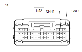
(b) Measure the resistance according to the value(s) in the table below.
Standard Resistance:
| Tester Connection | Condition | Specified Condition |
|---|---|---|
| I152-5 (CNH1) - I152-6 (CNL1) | Cable disconnected from negative (-) auxiliary battery terminal | 108 to 132 Ω |
| OK | | REPLACE RADIO RECEIVER ASSEMBLY |
| NG | | REPAIR OR REPLACE HARNESS OR CONNECTOR |
| 12. | CHECK HARNESS AND CONNECTOR (REMOTE OPERATION CONTROLLER ASSEMBLY [REMOTE TOUCH] - NO. 10 CAN JUNCTION CONNECTOR) |
| (a) Disconnect the remote operation controller assembly (remote touch) connector. |
|
(b) Measure the resistance according to the value(s) in the table below.
Standard Resistance:
| Tester Connection | Condition | Specified Condition |
|---|---|---|
| I71-9 (MO+) - I71-8 (MO-) | Cable disconnected from negative (-) auxiliary battery terminal | 108 to 132 Ω |
| OK | | REPLACE REMOTE OPERATION CONTROLLER ASSEMBLY (REMOTE TOUCH) |
| NG | | REPAIR OR REPLACE HARNESS OR CONNECTOR |
| 13. | CHECK HARNESS AND CONNECTOR (COMBINATION METER ASSEMBLY - NO. 10 CAN JUNCTION CONNECTOR) |
| (a) Disconnect the combination meter assembly connector. |
|
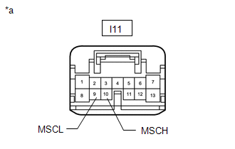
(b) Measure the resistance according to the value(s) in the table below.
Standard Resistance:
| Tester Connection | Condition | Specified Condition |
|---|---|---|
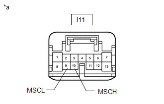
| I11-10 (MSCH) - I11-9 (MSCL) | Cable disconnected from negative (-) auxiliary battery terminal | 54 to 69 Ω |
| OK | | REPLACE COMBINATION METER ASSEMBLY |
| NG | | REPAIR OR REPLACE HARNESS OR CONNECTOR |
| 14. | CHECK HARNESS AND CONNECTOR (COMBINATION METER MIRROR ECU - NO. 10 CAN JUNCTION CONNECTOR) |
| (a) Disconnect the combination meter mirror ECU connector. |
|
(b) Measure the resistance according to the value(s) in the table below.
Standard Resistance:
| Tester Connection | Condition | Specified Condition |
|---|---|---|
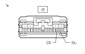
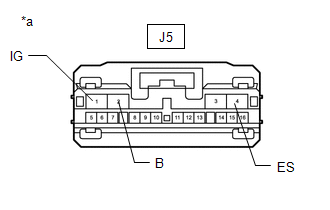
| J5-14 (CS) - J5-15 (TX-) | Cable disconnected from negative (-) auxiliary battery terminal | 54 to 69 Ω |
| OK | | REPLACE COMBINATION METER MIRROR ECU |
| NG | | REPAIR OR REPLACE HARNESS OR CONNECTOR |
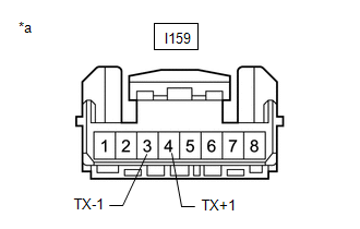
| 15. | CHECK HARNESS AND CONNECTOR (CLOCK ASSEMBLY - NO. 10 CAN JUNCTION CONNECTOR) |
| (a) Disconnect the clock assembly connector. |
|
(b) Measure the resistance according to the value(s) in the table below.
Standard Resistance:
| Tester Connection | Condition | Specified Condition |
|---|---|---|
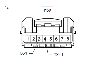
| I159-4 (TX+1) - I159-3 (TX-1) | Cable disconnected from negative (-) auxiliary battery terminal | 54 to 69 Ω |
| OK | | REPLACE CLOCK ASSEMBLY |
| NG | | REPAIR OR REPLACE HARNESS OR CONNECTOR |
| 16. | CHECK HARNESS AND CONNECTOR (COMBINATION METER ASSEMBLY POWER SOURCE) |
| (a) Disconnect the combination meter assembly connector. |
|
(b) Measure the resistance according to the value(s) in the table below.
Standard Resistance:
| Tester Connection | Condition | Specified Condition |
|---|---|---|
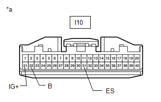
| I10-31 (ES) - Body ground | Always | Below 1 Ω |
(c) Measure the voltage according to the value(s) in the table below.
Standard Voltage:
| Tester Connection | Condition | Specified Condition |
|---|---|---|
| I10-22 (B) - Body ground | Power switch off | 11 to 14 V |
| I10-21 (IG+) - Body ground | Power switch on (IG) | 11 to 14 V |
| NG | | REPAIR OR REPLACE HARNESS OR CONNECTOR |
|
| 17. | CHECK HARNESS AND CONNECTOR (COMBINATION METER ASSEMBLY - NO. 10 CAN JUNCTION CONNECTOR) |
| (a) Disconnect the cable from the negative (-) auxiliary battery terminal. |
|
(b) Disconnect the combination meter assembly connector.
(c) Measure the resistance according to the value(s) in the table below.
Standard Resistance:
| Tester Connection | Condition | Specified Condition |
|---|---|---|
| I11-10 (MSCH) - I11-9 (MSCL) | Cable disconnected from negative (-) auxiliary battery terminal | 54 to 69 Ω |
| OK | | REPLACE COMBINATION METER ASSEMBLY |
| NG | | REPAIR OR REPLACE HARNESS OR CONNECTOR |
| 18. | CHECK HARNESS AND CONNECTOR (NO. 10 CAN JUNCTION CONNECTOR - RADIO RECEIVER ASSEMBLY) |
(a) Disconnect the cable from the negative (-) auxiliary battery terminal.
(b) Disconnect the No. 10 CAN junction connector.
| (c) Measure the resistance according to the value(s) in the table below. Standard Resistance:
|
|
| NG | | GO TO STEP 22 |
|
| 19. | CHECK HARNESS AND CONNECTOR (NO. 10 CAN JUNCTION CONNECTOR - REMOTE OPERATION CONTROLLER ASSEMBLY [REMOTE TOUCH]) |
(a) Disconnect the cable from the negative (-) auxiliary battery terminal.
(b) Disconnect the No. 10 CAN junction connector.
| (c) Measure the resistance according to the value(s) in the table below. Standard Resistance:
|
|
| OK | | REPLACE NO. 10 CAN JUNCTION CONNECTOR |
| NG | | GO TO STEP 23 |
| 20. | CHECK HARNESS AND CONNECTOR (COMBINATION METER MIRROR ECU POWER SOURCE) |
| (a) Disconnect the combination meter mirror ECU connector. |
|
(b) Measure the resistance according to the value(s) in the table below.
Standard Resistance:
| Tester Connection | Condition | Specified Condition |
|---|---|---|
| J5-4 (ES) - Body ground | Always | Below 1 Ω |
(c) Measure the voltage according to the value(s) in the table below.
Standard Voltage:
| Tester Connection | Condition | Specified Condition |
|---|---|---|
| J5-2 (B) - Body ground | Power switch off | 11 to 14 V |
| J5-1 (IG) - Body ground | Power switch on (IG) | 11 to 14 V |
| NG | | REPAIR OR REPLACE HARNESS OR CONNECTOR |
|
| 21. | CHECK HARNESS AND CONNECTOR (COMBINATION METER MIRROR ECU - NO. 10 CAN JUNCTION CONNECTOR) |
| (a) Disconnect the cable from the negative (-) auxiliary battery terminal. |
|
(b) Disconnect the combination meter mirror ECU connector.
(c) Measure the resistance according to the value(s) in the table below.
Standard Resistance:
| Tester Connection | Condition | Specified Condition |
|---|---|---|
| J5-14 (CS) - J5-15 (TX-) | Cable disconnected from negative (-) auxiliary battery terminal | 54 to 69 Ω |
| OK | | REPLACE COMBINATION METER MIRROR ECU |
| NG | | REPAIR OR REPLACE HARNESS OR CONNECTOR |
| 22. | CHECK HARNESS AND CONNECTOR (RADIO RECEIVER ASSEMBLY - NO. 10 CAN JUNCTION CONNECTOR) |
| (a) Disconnect the radio receiver assembly connector. |
|
(b) Measure the resistance according to the value(s) in the table below.
Standard Resistance:
| Tester Connection | Condition | Specified Condition |
|---|---|---|
| I152-5 (CNH1) - I152-6 (CNL1) | Cable disconnected from negative (-) auxiliary battery terminal | 108 to 132 Ω |
| OK | | REPLACE RADIO RECEIVER ASSEMBLY |
| NG | | REPAIR OR REPLACE HARNESS OR CONNECTOR |
| 23. | CHECK HARNESS AND CONNECTOR (REMOTE OPERATION CONTROLLER ASSEMBLY [REMOTE TOUCH] - NO. 10 CAN JUNCTION CONNECTOR) |
| (a) Disconnect the remote operation controller assembly (remote touch) connector. |
|
(b) Measure the resistance according to the value(s) in the table below.
Standard Resistance:
| Tester Connection | Condition | Specified Condition |
|---|---|---|
| I71-9 (MO+) - I71-8 (MO-) | Cable disconnected from negative (-) auxiliary battery terminal | 108 to 132 Ω |
| OK | | REPLACE REMOTE OPERATION CONTROLLER ASSEMBLY (REMOTE TOUCH) |
| NG | | REPAIR OR REPLACE HARNESS OR CONNECTOR |
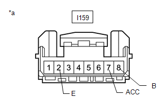
| 24. | CHECK HARNESS AND CONNECTOR (CLOCK ASSEMBLY POWER SOURCE) |
| (a) Disconnect the clock assembly connector. |
|
(b) Measure the resistance according to the value(s) in the table below.
Standard Resistance:
| Tester Connection | Condition | Specified Condition |
|---|---|---|
| I159-2 (E) - Body ground | Always | Below 1 Ω |
(c) Measure the voltage according to the value(s) in the table below.
Standard Voltage:
| Tester Connection | Condition | Specified Condition |
|---|---|---|
| I159-8 (B) - Body ground | Power switch off | 11 to 14 V |
| I159-7 (ACC) - Body ground | Power switch on (ACC) | 11 to 14 V |
| NG | | REPAIR OR REPLACE HARNESS OR CONNECTOR |
|
| 25. | CHECK HARNESS AND CONNECTOR (CLOCK ASSEMBLY - NO. 10 CAN JUNCTION CONNECTOR) |
| (a) Disconnect the cable from the negative (-) auxiliary battery terminal. |
|
(b) Disconnect the clock assembly connector.
(c) Measure the resistance according to the value(s) in the table below.
Standard Resistance:
| Tester Connection | Condition | Specified Condition |
|---|---|---|
| I159-4 (TX+1) - I159-3 (TX-1) | Cable disconnected from negative (-) auxiliary battery terminal | 54 to 69 Ω |
| OK | | REPLACE CLOCK ASSEMBLY |
| NG | | REPAIR OR REPLACE HARNESS OR CONNECTOR |
READ NEXT:
 HD Radio Tuner Malfunction (B1551,B15A0,B15B3,B15B5,B15B7,B15BA,B15F9)
DESCRIPTION These DTCs are stored when a malfunction occurs in the radio receiver assembly DTC No. Detection Item DTC Detection Condition Trouble Area B1551 HD Radio Tuner Malfunction
Touch Pad Sensor Malfunction (B1559)
DESCRIPTION This DTC is stored if the remote operation controller assembly (remote touch) detects a malfunction in itself, such as internal hardware failure or touch pad sensor malfunction. DTC No.
Touch Pad Vibration Driver Malfunction (B155A)
DESCRIPTION This DTC is stored if the remote operation controller assembly (remote touch) detects a malfunction in itself, such as internal hardware failure or touch pad vibration driver malfunction.
SEE MORE:
Removal
REMOVAL CAUTION / NOTICE / HINT CAUTION: Wear protective gloves. Sharp areas on the parts may injure your hands. HINT:
Use the same procedure for the RH and LH sides.
The procedure listed below is for the LH side.
PROCEDURE 1. REMOVE FRONT SEAT ASSEMBLY LH Click here 2. REMOVE FRONT LOWER
Front Airbag Sensor (LH) (B1615)
DESCRIPTION The front airbag sensor LH consists of a diagnostic circuit and frontal deceleration sensor, etc. If the airbag ECU assembly receives signals from the frontal deceleration sensor, it determines whether the SRS should be activated. DTC B1615 is stored when a malfunction is detected in the
