Lexus NX: Transmission Control Switch Circuit
DESCRIPTION
When the shift lever is in S, different ranges can be chosen using the floor shift sequential gate.
WIRING DIAGRAM
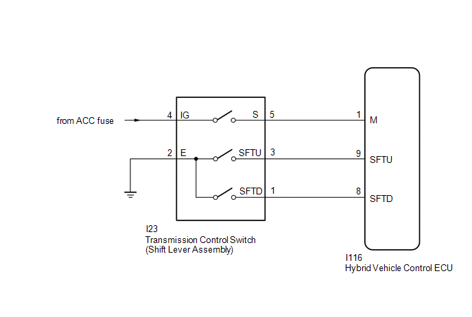
PROCEDURE
| 1. | READ VALUE USING TECHSTREAM (SPORTS MODE) |
(a) Connect the Techstream to the DLC3.
(b) Turn the power switch on (IG).
(c) Enter the following menus: Powertrain / Hybrid Control / Data List / Sports Mode.
Powertrain > Hybrid Control > Data List| Tester Display |
|---|
| Sports Mode |
(d) Read the value displayed on the Techstream.
Powertrain > Hybrid Control > Data List| Tester Display | Measurement Item | Range | Normal Condition |
|---|---|---|---|
| Sports Mode | Sports shift signal | ON or OFF | Shift lever in S: ON Shift lever not in S position: OFF |
| Result | Proceed to |
|---|---|
| The Techstream display changes according to the shift lever operation. | A |
| The Techstream display does not change according to the shift lever operation. | B |
(e) Turn the power switch off.
| B | .gif) | GO TO STEP 4 |
|
.gif)
| 2. | READ VALUE USING TECHSTREAM (SPORT UP SHIFT SENS STATE, SPORT DWN SHIFT SENS STATE) |
(a) Connect the Techstream to the DLC3.
(b) Turn the power switch on (IG).
(c) Enter the following menus: Powertrain / Hybrid Control / Data List / Sport Up Shift Sens State, Sport Dwn Shift Sens State.
Powertrain > Hybrid Control > Data List| Tester Display |
|---|
| Sport Up Shift Sens State |
| Sport Dwn Shift Sens State |
(d) Read the value displayed on the Techstream.
Powertrain > Hybrid Control > Data List| Tester Display | Measurement Item | Range | Normal Condition |
|---|---|---|---|
| Sport Up Shift Sens State | Sports shift UP signal | ON or OFF | Shift lever in "+" operated: ON Shift lever in S not operated: OFF |
| Sport Dwn Shift Sens State | Sport shift DOWN signal | ON or OFF | Shift lever in "-" operated: ON Shift lever in S not operated: OFF |
| Result | Proceed to |
|---|---|
| The Techstream display changes according to the transmission control switch (shift lever assembly) operation. | A |
| The Techstream display does not change according to the transmission control switch (shift lever assembly) operation. | B |
(e) Turn the power switch off.
| B | | GO TO STEP 7 |
|
| 3. | CHECK FOR INTERMITTENT PROBLEMS |
Click here .gif)
| OK | | REPLACE HYBRID VEHICLE CONTROL ECU |
| NG | | REPAIR OR REPLACE MALFUNCTIONING PARTS, COMPONENT AND AREA |
| 4. | CHECK HARNESS AND CONNECTOR (POWER SOURCE CIRCUIT) |
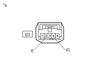
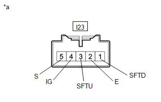
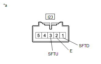
(a) Disconnect the I23 transmission control switch (shift lever assembly) connector.
Click here
| (b) Measure the voltage according to the value(s) in the table below. Standard Voltage:
|
|
(c) Turn the power switch off.
(d) Measure the resistance according to the value(s) in the table below.
Standard Resistance:
| Tester Connection | Condition | Specified Condition |
|---|---|---|
| I23-2 (E) - Body ground | Power switch off | Below 1 Ω |
(e) Reconnect the I23 transmission control switch (shift lever assembly) connector.
| NG | | CHECK POWER SOURCE CIRCUIT |
|
| 5. | INSPECT TRANSMISSION CONTROL SWITCH (SHIFT LEVER ASSEMBLY) |
(a) Disconnect the I23 transmission control switch (shift lever assembly) connector.
| (b) Measure the resistance according to the value(s) in the table below when the shift lever is moved to each position. Standard Resistance:
|
|
(c) Reconnect the I23 transmission control switch (shift lever assembly) connector.
| NG | | REPLACE TRANSMISSION CONTROL SWITCH (SHIFT LEVER ASSEMBLY) |
|
| 6. | CHECK HARNESS AND CONNECTOR (HYBRID VEHICLE CONTROL ECU - TRANSMISSION CONTROL SWITCH (SHIFT LEVER ASSEMBLY)) |
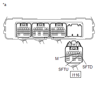
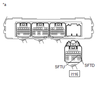
| (a) Disconnect the I116 hybrid vehicle control ECU connector. |
|
(b) Turn the power switch on (IG).
(c) Measure the voltage according to the value(s) in the table below when the shift lever is moved to each position.
Standard Voltage:
| Tester Connection | Condition | Specified Condition |
|---|---|---|
| I116-1 (M) - Body ground | Power switch on (IG) S, "+" and "-" | 11 to 14 V |
| I116-1 (M) - Body ground | Power switch on (IG) Except S, "+" and "-" | Below 1 V |
NOTICE:
If the power switch is turned on (IG) with the hybrid vehicle control ECU connector disconnected, other DTCs will be stored. After performing the inspection, clear the DTCs.
(d) Measure the resistance according to the value(s) in the table below when the shift lever is moved to each position.
Standard Resistance:
| Tester Connection | Condition | Specified Condition |
|---|---|---|
| I116-9 (SFTU) - Body ground | Shift lever in S Shift lever held in "+" | Below 1 Ω |
| I116-8 (SFTD) - Body ground | Shift lever in S Shift lever held in "-" | Below 1 Ω |
| I116-9 (SFTU) - Body ground | Shift lever in S | 10 kΩ or higher |
| I116-8 (SFTD) - Body ground | Shift lever in S | 10 kΩ or higher |
(e) Turn the power switch off.
(f) Reconnect the I116 hybrid vehicle control ECU connector.
| OK | | REPLACE HYBRID VEHICLE CONTROL ECU |
| NG | | REPAIR OR REPLACE HARNESS OR CONNECTOR |
| 7. | INSPECT TRANSMISSION CONTROL SWITCH (SHIFT LEVER ASSEMBLY) |
(a) Disconnect the I23 transmission control switch (shift lever assembly ) connector.
Click here
| (b) Measure the resistance according to the value(s) in the table below when the shift lever is moved to each position. Standard Resistance:
|
|
(c) Reconnect the I23 transmission control switch (shift lever assembly ) connector.
| NG | | REPLACE TRANSMISSION CONTROL SWITCH (SHIFT LEVER ASSEMBLY) |
|
| 8. | CHECK HARNESS AND CONNECTOR (TRANSMISSION CONTROL SWITCH (SHIFT LEVER ASSEMBLY) - HYBRID VEHICLE CONTROL ECU) |
(a) Disconnect the I116 hybrid vehicle control ECU connector.
| (b) Measure the resistance according to the value(s) in the table below when the shift lever is moved to each position. Standard Resistance:
|
|
(c) Reconnect the I116 hybrid vehicle control ECU connector.
| OK | | REPLACE HYBRID VEHICLE CONTROL ECU |
| NG | | REPAIR OR REPLACE HARNESS OR CONNECTOR |
READ NEXT:
 Shift Paddle Switch Circuit
DESCRIPTION When the shift lever is in S, the shift range position can be changed freely using the shift paddle switch of the transmission shift switch assembly. WIRING DIAGRAM PROCEDURE 1. REA
Pattern Select Switch EV Mode Circuit
DESCRIPTION The EV drive mode signal will be sent to the hybrid vehicle control ECU when the EV drive mode switch (integration control & panel assembly) is operated. If the specified conditions ar
Pattern Select Switch Sport Mode Circuit
DESCRIPTION When selecting SPORT mode, the switch operation signal is sent to the ECM. Following this, the drive torque is optimally controlled to obtain a sporty feel in response to the driver's acce
SEE MORE:
Terminals Of Ecm
TERMINALS OF ECM HINT: The standard voltage, resistance and waveform between each pair of the ECM terminals is shown in the table below. The appropriate conditions for checking each pair of the terminals is also indicated. The result of checks should be compared with the standard voltage, resistanc
Customize Parameters
CUSTOMIZE PARAMETERS CUSTOMIZE ROAD SIGN ASSIST SYSTEM NOTICE: Be sure to make a note of the current settings before customizing. (a) Customizing with the multi-information display (1) Turn the power switch on (IG). (2) Using the steering pad switches, change the customize settings. HINT: Each item
