Lexus NX: Low or High Power Supply Voltage (C1241,C1242)
DESCRIPTION
If a malfunction is detected in the power supply circuit, the skid control ECU (brake booster with master cylinder assembly) power source voltage drops, or there is insufficient voltage to operate the ABS main relay, the skid control ECU (brake booster with master cylinder assembly) will store these DTCs.
These DTCs may also be stored if the auxiliary battery voltage drops below 9.5 V.
HINT:
DTC C1256 (Accumulator Low Pressure) may also be memorized if there is a drop in power source voltage.
| DTC No. | Detection Item | INF Code | DTC Detection Condition | Trouble Area | Note |
|---|---|---|---|---|---|
| C1241 | Low or High Power Supply Voltage | 101 102 551 552 553 |
|
| - |
| C1242 | Open Circuit in IG1/IG2 Power Source Circuit | 111 112 |
|
| - |
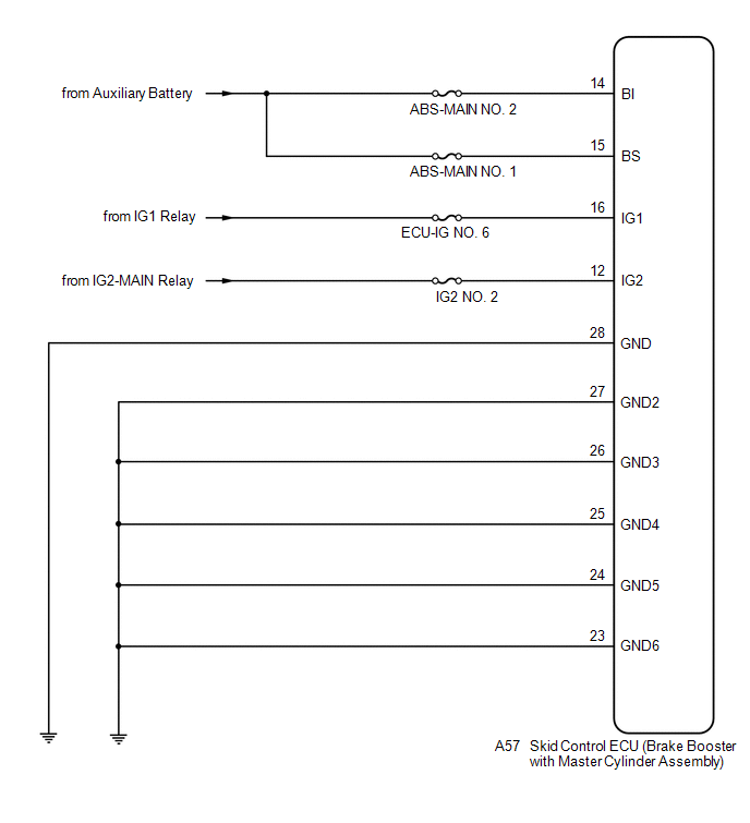
WIRING DIAGRAM
CAUTION / NOTICE / HINT
NOTICE:
-
When replacing the skid control ECU (brake booster with master cylinder assembly), perform initialization and calibration of the linear solenoid valve.
Click here
.gif)
- Inspect the fuses for circuits related to this system before performing the following procedure.
PROCEDURE
| 1. | CHECK SMART ACCESS SYSTEM WITH PUSH-BUTTON START (for Start Function) |
(a) Check if smart access system with push-button start (for start function) DTCs are output.
Click here
| Result | Proceed to |
|---|---|
| DTCs are not output. | A |
| DTCs are output. | B |
| B | .gif) | INSPECT SMART ACCESS SYSTEM WITH PUSH-BUTTON START (for Start Function) |
|
.gif)
| 2. | CHECK HYBRID CONTROL SYSTEM |
(a) Check if hybrid control system DTCs are output.
Click here
| Result | Proceed to |
|---|---|
| DTCs are not output. | A |
| DTCs are output. | B |
| B | | INSPECT HYBRID CONTROL SYSTEM |
|
| 3. | CHECK DTC |
(a) Check that no main relay malfunction DTCs are output.
Click here
| Result | Proceed to |
|---|---|
| Main relay malfunction DTCs are not output. | A |
| Main relay malfunction DTCs are output. | B |
| B | | REPAIR CIRCUITS INDICATED BY OUTPUT DTCS |
|
| 4. | CHECK AUXILIARY BATTERY |
(a) Check the auxiliary battery voltage.
Standard Voltage:
| Tester Connection | Switch Condition | Specified Condition |
|---|---|---|
| Auxiliary battery | Power switch on (IG) | 11 to 14 V |
| Auxiliary battery | Power switch on (READY) | 11 to 15.5 V |
| NG | | CHARGE OR REPLACE AUXILIARY BATTERY |
|
| 5. | CHECK HARNESS AND CONNECTOR (POWER SOURCE TERMINAL) |
| (a) Make sure that there is no looseness at the locking part and the connecting part of the connector. |
|
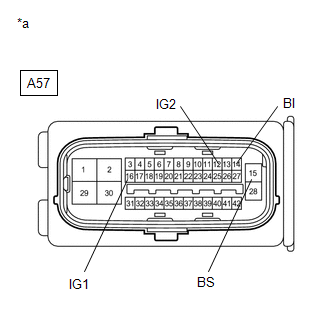
(b) Disconnect the A57 skid control ECU (brake booster with master cylinder assembly) connector.
(c) Measure the voltage according to the value(s) in the table below.
Standard Voltage:
| Tester Connection | Condition | Specified Condition |
|---|---|---|
| A57-14 (BI) - Body ground | Always | 11 to 14 V |
| A57-15 (BS) - Body ground | Always | 11 to 14 V |
| A57-16 (IG1) - Body ground | Power switch on (IG) | 11 to 14 V |
| A57-12 (IG2) - Body ground | Power switch on (IG) | 11 to 14 V |
| NG | | REPAIR OR REPLACE HARNESS OR CONNECTOR (POWER SOURCE CIRCUIT) |
|
| 6. | CHECK HARNESS AND CONNECTOR (GND TERMINAL) |
| (a) Turn the power switch off. |
|
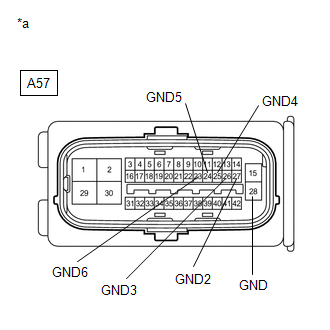
(b) Measure the resistance according to the value(s) in the table below.
Standard Resistance:
| Tester Connection | Condition | Specified Condition |
|---|---|---|
| A57-28 (GND) - Body ground | Always | Below 1 Ω |
| A57-27 (GND2) - Body ground | Always | Below 1 Ω |
| A57-26 (GND3) - Body ground | Always | Below 1 Ω |
| A57-25 (GND4) - Body ground | Always | Below 1 Ω |
| A57-24 (GND5) - Body ground | Always | Below 1 Ω |
| A57-23 (GND6) - Body ground | Always | Below 1 Ω |
| NG | | REPAIR OR REPLACE HARNESS OR CONNECTOR (GND CIRCUIT) |
|
| 7. | RECONFIRM DTC |
(a) Reconnect the A57 skid control ECU (brake booster with master cylinder assembly) connector.
(b) Clear the DTCs.
Click here
(c) Turn the power switch off.
(d) Turn the power switch on (READY).
(e) Perform a road test.
(f) Check if the same DTC is output.
Click here
| Result | Proceed to |
|---|---|
| DTCs C1241 and C1242 are not output. | A |
| DTCs C1241 and/or C1242 are output. | B |
HINT:
If troubleshooting has been carried out according to Problem Symptoms Table, refer back to the table and proceed to the next step.
Click here
| A | | USE SIMULATION METHOD TO CHECK |
| B | | REPLACE BRAKE BOOSTER WITH MASTER CYLINDER ASSEMBLY |
READ NEXT:
 Master Cylinder Pressure Sensor (C1246,C1281,C1364)
DESCRIPTION The regulator pressure sensor and wheel cylinder pressure sensor are built into the brake actuator. They measure their respective pressures and send signals to the skid control ECU (brake
Stroke Sensor (C1247,C1346,C1392)
DESCRIPTION The brake pedal stroke sensor assembly sends a signal about the pedal stroke to the skid control ECU (brake booster with master cylinder assembly). DTC C1346 will be cleared when the brake
Open Circuit in Stop Light Switch Circuit (C1249)
DESCRIPTION The skid control ECU (brake booster with master cylinder assembly) receives the stop light switch assembly signal and detects the brake pedal operation status. The skid control ECU (brake
SEE MORE:
Components
COMPONENTS ILLUSTRATION *1 DECK FLOOR BOX LH *2 NO. 3 DECK BOARD SUB-ASSEMBLY *3 REAR DECK FLOOR BOX *4 NEGATIVE AUXILIARY BATTERY TERMINAL N*m (kgf*cm, ft.*lbf): Specified torque - - ILLUSTRATION *1 BATTERY SERVICE HOLE COVER *2 HYBRID BATTERY SERVICE PLU
Installation
INSTALLATION CAUTION / NOTICE / HINT HINT:
Use the same procedure for the RH and LH sides.
The procedure described below is for the LH side.
PROCEDURE 1. INSTALL LICENSE PLATE LIGHT ASSEMBLY LH (a) Attach the 2 claws to install the license plate light assembly LH. (b) Connect the connector.
