Lexus NX: Mute Signal Circuit between Stereo Component Amplifier and Telematics Transceiver
DESCRIPTION
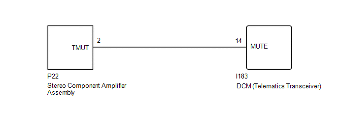
This DCM (telematics transceiver) sends a mute signal to the stereo component amplifier assembly. The stereo component amplifier assembly controls the volume according to the mute signal from the DCM (telematics transceiver).
If there is an open in the circuit, noise can be heard from the speakers when changing the sound source.
If there is a short in the circuit, even though the stereo component amplifier assembly is functioning normally, no sound or only an extremely faint sound can be heard.
WIRING DIAGRAM
CAUTION / NOTICE / HINT
NOTICE:
When replacing the DCM (telematics transceiver), make sure to replace it with a new one.
HINT:
Depending on the parts that are replaced during vehicle inspection or maintenance, performing initialization, registration or calibration may be needed. Refer to Precaution for Navigation System.
Click here .gif)
PROCEDURE
| 1. | INSPECT DCM (TELEMATICS TRANSCEIVER) |
| (a) Remove the DCM (telematics transceiver) with the connector(s) still connected. Click here |
|
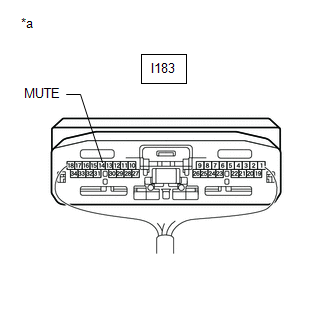
(b) Measure the voltage according to the value(s) in the table below.
Standard Voltage:
| Tester Connection | Switch Condition | Specified Condition |
|---|---|---|
| I183-14 (MUTE) - Body ground | Power switch on (IG), audio system playing → Emergency call mode | 3.0 to 5.0 V → Below 1 V |
| OK | .gif) | PROCEED TO NEXT SUSPECTED AREA SHOWN IN PROBLEM SYMPTOMS TABLE |
|
.gif)
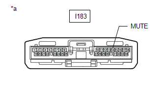
| 2. | CHECK HARNESS AND CONNECTOR (STEREO COMPONENT AMPLIFIER ASSEMBLY - DCM [TELEMATICS TRANSCEIVER]) |
(a) Disconnect the P22 stereo component amplifier assembly connector.
(b) Disconnect the I183 DCM (telematics transceiver) connector.
(c) Measure the resistance according to the value(s) in the table below.
Standard Resistance:
| Tester Connection | Condition | Specified Condition |
|---|---|---|
| P22-2 (TMUT) - I183-14 (MUTE) | Always | Below 1 Ω |
| P22-2 (TMUT) - Body ground | Always | 10 kΩ or higher |
| NG | | REPAIR OR REPLACE HARNESS OR CONNECTOR |
|
| 3. | CHECK STEREO COMPONENT AMPLIFIER ASSEMBLY |
(a) Disconnect the DCM (telematics transceiver) connector.
| (b) Measure the voltage according to the value(s) in the table below. Standard Voltage:
|
|
| OK | | REPLACE DCM (TELEMATICS TRANSCEIVER) |
| NG | | REPLACE STEREO COMPONENT AMPLIFIER ASSEMBLY |
READ NEXT:
 AVC-LAN Circuit
DESCRIPTION Each audio system component connected to the AVC-LAN (communication bus) transfers switch signals using the audio visual communication local area network. If a short to +B or short to grou
Vehicle Speed Signal Circuit between Navigation ECU and Combination Meter
DESCRIPTION The navigation ECU receives a vehicle speed signal from the combination meter assembly. HINT:
A voltage of 12 V or 5 V is output from each ECU and then input to the combination meter as
Vehicle Speed Signal Circuit between Stereo Component Amplifier and Combination Meter
DESCRIPTION The stereo component amplifier assembly receives a vehicle speed signal from the combination meter assembly to control the ASL function. HINT:
A voltage of 12 V or 5 V is output from ea
SEE MORE:
System Description
SYSTEM DESCRIPTION
The power steering system generates torque through the operation of the motor and the reduction gear installed on the column shaft in order to assist steering effort.
The power steering ECU assembly determines the direction and the amount of assist power in accordance with ve
Sound Quality is Bad Only when Disc is Played (Volume is Too Low)
CAUTION / NOTICE / HINT NOTICE: When replacing the radio receiver assembly, always replace it with a new one. If a radio receiver assembly which was installed to another vehicle is used, the following may occur:
A communication malfunction DTC may be stored.
The radio receiver assembly may not
