Lexus NX: Installation
INSTALLATION
PROCEDURE
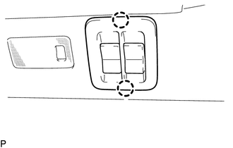
1. INSTALL NO. 2 FOLD SEAT SWITCH ASSEMBLY (for Rear Side)
| (a) Connect the connector. |
|
.png)
| (b) Attach the 2 claws to install the No. 2 fold seat switch assembly. |
|
2. INSTALL REAR POWER SEAT SWITCH (for Rear Seat)
HINT:
Use the same procedure for both rear power seat switches.
| (a) Attach the 2 claws to install the rear power seat switch. |
|
.png)
3. INSTALL NO. 3 BATTERY SERVICE COVER BOARD (for Rear Seat)
Click here .gif)
4. INSTALL NO. 2 BATTERY SERVICE COVER BOARD (for Rear Seat)
Click here
5. INSTALL BENCH TYPE REAR SEAT CUSHION ASSEMBLY (for Rear Seat)
Click here
6. INSTALL NO. 1 FOLD SEAT SWITCH ASSEMBLY (for Front Side)
| (a) Attach the 4 claws to install the No. 1 fold seat switch assembly. |
|
.png)
7. INSTALL LOWER NO. 1 INSTRUMENT PANEL FINISH PANEL (for Front Side)
Click here
8. INSTALL NO. 1 INSTRUMENT PANEL UNDER COVER SUB-ASSEMBLY (for Front Side)
Click here
9. INSTALL NO. 1 INSTRUMENT PANEL SAFETY PAD SUB-ASSEMBLY (for Front Side)
Click here
10. INSTALL INSTRUMENT SIDE PANEL LH (for Front Side)
Click here
11. INSTALL COWL SIDE TRIM BOARD LH (for Front Side)
Click here
12. INSTALL DOOR SCUFF PLATE ASSEMBLY LH (for Front Side)
Click here
13. INSTALL UPPER NO. 2 CONSOLE PANEL GARNISH (for Front Side)
Click here
14. INSTALL CONSOLE ARMREST ASSEMBLY (for Front Side)
Click here
READ NEXT:
 Precaution
PRECAUTION POWER FOLDING SEAT FUNCTION HANDLING PRECAUTIONS NOTICE:
When operating the rear power seat, make sure nothing is in the path of movement.
When operating the rear power seat, do not al
Parts Location
PARTS LOCATION ILLUSTRATION *1 REAR POWER SEAT SWITCH (REAR RIGHT SEAT) *2 REAR POWER SEAT SWITCH (REAR LEFT SEAT) *3 NO. 2 FOLD SEAT SWITCH ASSEMBLY *4 REAR SEATBACK FRAME SUB-ASS
SEE MORE:
If the electronic key does not operate
properly
If communication between the
electronic key and vehicle is interrupted or the electronic
key cannot be used because the
battery is depleted, the smart
access system with push-button
start and wireless remote control
cannot be used. In such cases, the
doors can be opened and the hybrid
system
STSW Monitor Malfunction (B2275)
DESCRIPTION This DTC is stored when a malfunction is detected in the starter circuit inside the certification ECU (smart key ECU assembly). DTC No. Detection Item DTC Detection Condition Trouble Area Note B2275 STSW Monitor Malfunction Certification ECU (smart key ECU assembly) in
