Lexus NX: No Answer-Back
DESCRIPTION
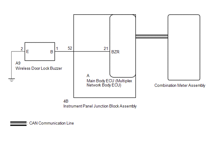
In some cases, wireless door lock control functions are normal but the hazard warning light and/or wireless door lock buzzer answer-back function does not operate. In such cases, hazard warning light and wireless door lock buzzer signal outputs from the main body ECU (multiplex network body ECU) may be malfunctioning.
WIRING DIAGRAM
CAUTION / NOTICE / HINT
NOTICE:
-
The wireless door lock control system key reminder warning system uses the CAN communication system. Inspect the communication function by following How to Proceed with Troubleshooting. Troubleshoot the wireless door lock control system after confirming that the communication system is functioning properly.
Click here
.gif)
-
If the main body ECU (multiplex network body ECU) is replaced, refer to the Smart Access System with Push-button Start (for Entry Function).
Click here
PROCEDURE
| 1. | CHECK CUSTOMIZE SETTING |
(a) Connect the Techstream to the DLC3.
(b) Turn the power switch on (IG).
(c) Turn the Techstream on.
(d) Enter the following menus: Customize Setting / Wireless Door Lock.
(e) Select the setting by referring to the table below.
Wireless Door Lock| Tester Display | Description | Default | Setting | ECU |
|---|---|---|---|---|
| Hazard Answer Back | When the doors are locked by wireless operation, the hazard warning lights flash once. When the doors are unlocked by wireless operation, the hazard warning lights flash twice. | ON | 0:OFF,1:ON | Main body ECU (Multiplex network body ECU) |
| Wireless Buzzer Resp | Wireless door lock buzzer response | ON | 0:OFF,1:ON | Main body ECU (Multiplex network body ECU) |
| Wireless Buzzer Vol | Wireless door lock buzzer volume | Level5 | 0000:Level7,0001:Level6,0010:Level5,0011:Level4,0100:Level3,0101:Level2,0110:Level1,0111:Level0 | Main body ECU (Multiplex network body ECU) |
| Result | Proceed to |
|---|---|
| Both items are ON and except Level 0 | A |
| Either item is OFF or Level 0 | B |
| B | .gif) | PERFORM CUSTOMIZE FUNCTION |
|
.gif)
| 2. | CHECK WIRELESS DOOR LOCK CONTROL FUNCTIONS |
(a) Check the wireless door lock control function using the electrical key transmitter sub-assembly.
| Result | Proceed to |
|---|---|
| Wireless door lock/unlock operates properly. | A |
| Wireless door lock/unlock does not operate properly. | B |
| B | | GO TO PROBLEM SYMPTOMS TABLE |
|
| 3. | READ VALUE USING TECHSTREAM (FR Door Lock Pos, FL Door Lock Pos, RR-Door Lock Pos SW, RL-Door Lock Pos SW) |
(a) Connect the Techstream to the DLC3.
(b) Turn the power switch on (IG).
(c) Turn the Techstream on.
(d) Enter the following menus: Body Electrical / Main Body / Data List.
(e) Read the Data List according to the display on the Techstream.
Body Electrical > Main Body > Data List| Tester Display | Measurement Item | Range | Normal Condition | Diagnostic Note |
|---|---|---|---|---|
| FR Door Lock Pos | Front door RH unlock detection switch signal | LOCK or UNLOCK | LOCK: Front door RH locked UNLOCK: Front door RH unlocked | - |
| FL Door Lock Pos | Front door LH unlock detection switch signal | LOCK or UNLOCK | LOCK: Front door LH locked UNLOCK: Front door LH unlocked | - |
| RR-Door Lock Pos SW | Rear door RH unlock detection switch signal | OFF or ON | OFF: Rear door RH locked ON: Rear door RH unlocked | - |
| RL-Door Lock Pos SW | Rear door LH unlock detection switch signal | OFF or ON | OFF: Rear door LH locked ON: Rear door LH unlocked | - |
| Tester Display |
|---|
| FR Door Lock Pos |
| FL Door Lock Pos |
| RR-Door Lock Pos SW |
| RL-Door Lock Pos SW |
OK:
The Techstream display changes correctly in response to the lock/unlock operation.
| NG | | GO TO LIGHTING SYSTEM (Proceed to Door Unlock Detection Switch Circuit) |
|
| 4. | CHECK WIRELESS ANSWER-BACK OPERATION |
(a) Check the wireless answer-back operation using the electrical key transmitter sub-assembly.
| Result | Proceed to |
|---|---|
| Only wireless door lock buzzer answer-back does not occur. | A |
| Only hazard warning light answer-back does not occur. | B |
| A | | GO TO SMART ACCESS SYSTEM WITH PUSH-BUTTON START (for Entry Function) (Entry Exterior Alarm and Answer-back Buzzer do not Sound) |
|
| 5. | CHECK HAZARD WARNING LIGHTS OPERATION |
(a) Check that the hazard warning lights blink when the hazard warning signal switch is pressed.
OK:
Hazard warning lights blink.
| OK | | REPLACE MAIN BODY ECU (MULTIPLEX NETWORK BODY ECU) |
| NG | | GO TO LIGHTING SYSTEM (Proceed to Hazard Warning Switch Circuit) |
READ NEXT:
 Air Conditioning Amplifier
ComponentsCOMPONENTS ILLUSTRATION *1 AIR CONDITIONING AMPLIFIER ASSEMBLY *2 INNER NO. 1 INSTRUMENT PANEL BRACE COVER RH RemovalREMOVAL PROCEDURE 1. REMOVE INNER NO. 1 INSTRUMENT PANEL B
SEE MORE:
Fuel information
You must only use unleaded gasoline
in your vehicle.
Select octane rating 87 (Research
Octane Number 91) or higher. Use
of unleaded gasoline with an octane
rating lower than 87 may result in
engine knocking. Persistent knocking
can lead to engine damage.
At minimum, the gasoline you use
s
Installation
INSTALLATION CAUTION / NOTICE / HINT PROCEDURE 1. INSTALL QUARTER OUTSIDE MOULDING SUB-ASSEMBLY LH HINT: When installing the quarter outside moulding sub-assembly LH, heat the vehicle body and quarter outside moulding sub-assembly LH using a heat light. Standard: Item Temperature Vehicle B
