Lexus NX: No Response from ID BOX (B2789)
DESCRIPTION
This DTC is stored when LIN communication between the certification ECU (smart key ECU assembly) and ID code box (immobiliser code ECU) stops for 10 seconds or more.
| DTC No. | Detection Item | DTC Detection Condition | Trouble Area |
|---|---|---|---|
| B2789 | No Response from ID BOX | No communication between the certification ECU and ID code box for 10 seconds or more. |
|
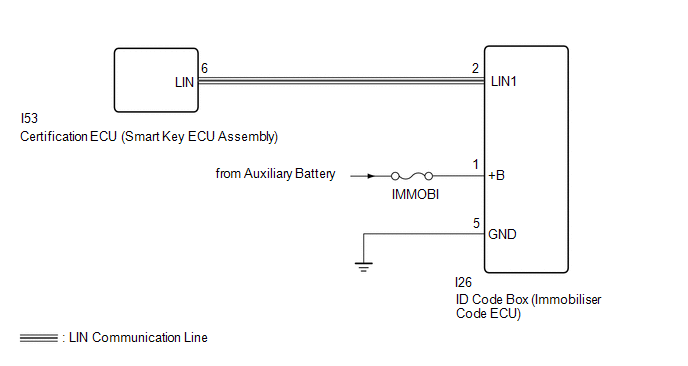
WIRING DIAGRAM
CAUTION / NOTICE / HINT
NOTICE:
-
When using the Techstream with the power switch off to troubleshoot:
Connect the Techstream to the vehicle, and turn a courtesy light switch on and off at 1.5 second intervals until communication between the Techstream and vehicle begins.
- Inspect the fuses for circuits related to this system before performing the following inspection procedure.
- Before replacing the certification ECU (smart key ECU assembly) or immobiliser code ECU, refer to the immobiliser system.
HINT:
When the communication between the ID code box (immobiliser code ECU) and certification ECU (smart key ECU assembly) stops, DTC B2785 is also stored.
PROCEDURE
| 1. | CLEAR DTC |
(a) Clear the DTCs.
Click here .gif)
|
.gif)
| 2. | CHECK FOR DTC |
(a) Check for DTCs.
Click here
| DTC B2789 is not output | .gif) | USE SIMULATION METHOD TO CHECK |
|
| 3. | CHECK HARNESS AND CONNECTOR (CERTIFICATION ECU [SMART KEY ECU ASSEMBLY] - ID CODE BOX [IMMOBILISER CODE ECU]) |
(a) Disconnect the I53 certification ECU (smart key ECU assembly) connector.
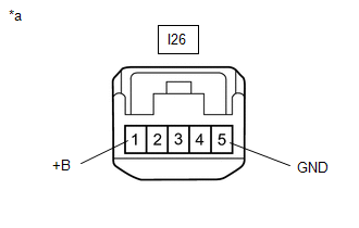
(b) Disconnect the I26 ID code box (immobiliser code ECU) connector.
(c) Measure the resistance according to the value(s) in the table below.
Standard Resistance:
| Tester Connection | Condition | Specified Condition |
|---|---|---|
| I53-6 (LIN) - I26-2 (LIN1) | Always | Below 1 Ω |
| I53-6 (LIN) - Body ground | Always | 10 kΩ or higher |
| NG | | REPAIR OR REPLACE HARNESS OR CONNECTOR |
|
| 4. | CHECK HARNESS AND CONNECTOR (ID CODE BOX [IMMOBILISER CODE ECU] - BATTERY AND BODY GROUND) |
| (a) Disconnect the ID code box (immobiliser code ECU) connector. |
|
(b) Measure the resistance according to the value(s) in the table below.
Standard Resistance:
| Tester Connection | Condition | Specified Condition |
|---|---|---|
| I26-5 (GND) - Body ground | Always | Below 1 Ω |
(c) Measure the voltage according to the value(s) in the table below.
Standard Voltage:
| Tester Connection | Switch Condition | Specified Condition |
|---|---|---|
| I26-1 (+B) - Body ground | Power switch off | 11 to 14 V |
| NG | | REPAIR OR REPLACE HARNESS OR CONNECTOR |
|
| 5. | REPLACE CERTIFICATION ECU (SMART KEY ECU ASSEMBLY) |
(a) Temporarily replace the certification ECU (smart key ECU assembly) with a new one.
Click here
(b) Clear the DTCs.
Click here
|
| 6. | CHECK FOR DTC |
(a) Check for DTCs.
Click here
| DTC B2789 is not output | | END (CERTIFICATION ECU [SMART KEY ECU ASSEMBLY] IS DEFECTIVE) |
| DTC B2789 is output | | REPLACE ID CODE BOX (IMMOBILISER CODE ECU) |
READ NEXT:
 Rain Sensor LIN Communication Malfunction
DESCRIPTION A malfunction occurs in LIN communication of the components related to the rain sensor between the rain sensor and windshield wiper relay assembly. WIRING DIAGRAM CAUTION / NOTICE / HINT
Air Conditioning Control Panel does not Operate
DESCRIPTION A malfunction occurs in LIN communication of the components related to the air conditioning between the air conditioning amplifier and air conditioning control. WIRING DIAGRAM CAUTION / N
Network Gateway Ecu
ComponentsCOMPONENTS ILLUSTRATION *1 NETWORK GATEWAY ECU - - RemovalREMOVAL PROCEDURE 1. REMOVE ECU INTEGRATION BOX RH Click here 2. REMOVE NETWORK GATEWAY ECU (a) Detach the 2 claws
SEE MORE:
Components
COMPONENTS ILLUSTRATION *A for Manual Seat *B for Power Seat *1 NO. 2 BATTERY SERVICE COVER BOARD *2 NO. 3 BATTERY SERVICE COVER BOARD *3 REAR DOOR SCUFF PLATE LH *4 REAR DOOR SCUFF PLATE RH *5 REAR SEAT CUSHION ASSEMBLY *6 RECLINING ADJUSTER RELEASE HANDLE LH
Components
COMPONENTS ILLUSTRATION *1 DECK FLOOR BOX LH *2 REAR DECK FLOOR BOX *3 UPPER INSTRUMENT PANEL *4 AUXILIARY BATTERY NEGATIVE TERMINAL N*m (kgf*cm, ft.*lbf): Specified torque - - ILLUSTRATION *1 INSTRUMENT PANEL PASSENGER AIRBAG ASSEMBLY *2 NO. 2 INSTRUMENT
