Lexus NX: Air Conditioning Control Panel does not Operate
DESCRIPTION
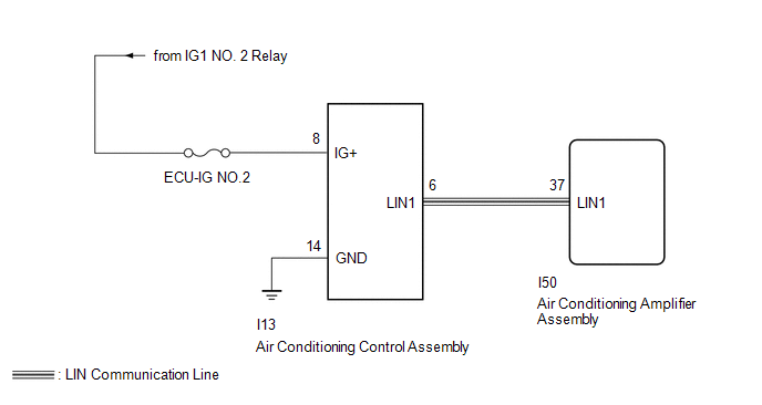
A malfunction occurs in LIN communication of the components related to the air conditioning between the air conditioning amplifier and air conditioning control.
WIRING DIAGRAM
CAUTION / NOTICE / HINT
NOTICE:
-
When using the Techstream with the power switch off to troubleshoot:
Connect the Techstream to the vehicle, and turn a courtesy light switch on and off at 1.5 second intervals until communication between the Techstream and vehicle begins.
- Inspect the fuses for circuits related to this system before performing the following inspection procedure.
PROCEDURE
| 1. | CHECK HARNESS AND CONNECTOR (AIR CONDITIONING CONTROL ASSEMBLY - BATTERY AND BODY GROUND) |
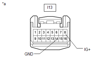
| *a | Front view wire harness connector (to Air Conditioning Control Assembly) |
(a) Disconnect the air conditioning control assembly connector.
(b) Measure the resistance according to the value(s) in the table below.
Standard Resistance:
| Tester Connection | Condition | Specified Condition |
|---|---|---|
| I13-14 (GND) - Body ground | Always | Below 1 Ω |
(c) Measure the voltage according to the value(s) in the table below.
Standard Voltage:
| Tester Connection | Switch Condition | Specified Condition |
|---|---|---|
| I13-8 (IG+) - Body ground | Power switch on (IG) | 11 to 14 V |
| NG | .gif) | REPAIR OR REPLACE HARNESS OR CONNECTOR |
|
.gif)
| 2. | CHECK HARNESS AND CONNECTOR (AIR CONDITIONING AMPLIFIER ASSEMBLY - AIR CONDITIONING CONTROL ASSEMBLY) |
(a) Disconnect the I50 air conditioning control assembly connector.
(b) Disconnect the I13 air conditioning amplifier assembly connector.
(c) Measure the resistance according to the value(s) in the table below.
Standard Resistance:
| Tester Connection | Condition | Specified Condition |
|---|---|---|
| I50-37 (LIN1) - I13-6 (LIN1) | Always | Below 1 Ω |
| I50-37 (LIN1) or I13-6 (LIN1) - Body ground | Always | 10 kΩ or higher |
| OK | | GO TO AIR CONDITIONING SYSTEM |
.gif)
| NG | | REPAIR OR REPLACE HARNESS OR CONNECTOR |
READ NEXT:
 Network Gateway Ecu
ComponentsCOMPONENTS ILLUSTRATION *1 NETWORK GATEWAY ECU - - RemovalREMOVAL PROCEDURE 1. REMOVE ECU INTEGRATION BOX RH Click here 2. REMOVE NETWORK GATEWAY ECU (a) Detach the 2 claws
SEE MORE:
CAN Communication Failure (Message Registry) (U1000)
DESCRIPTION If DTC U1000 is stored frequently, duplicate the conditions that cause the problem symptoms and perform the inspection again even if the DTC is not output when rechecking for DTCs. DTC No. Detection Item DTC Detection Condition Trouble Area U1000 CAN Communication Failure
Installation
INSTALLATION PROCEDURE 1. INSTALL FRONT LUMBAR POWER SEAT SWITCH (a) Attach the 4 claws to install the front lumbar power seat switch. 2. INSTALL FRONT POWER SEAT SWITCH LH Click here 3. INSTALL FRONT SEAT CUSHION SHIELD LH Click here 4. INSTALL POWER SEAT SWITCH KNOB LH Click here 5. INSTALL
