Lexus NX: Occupant Classification System Malfunction (B1650)
DESCRIPTION
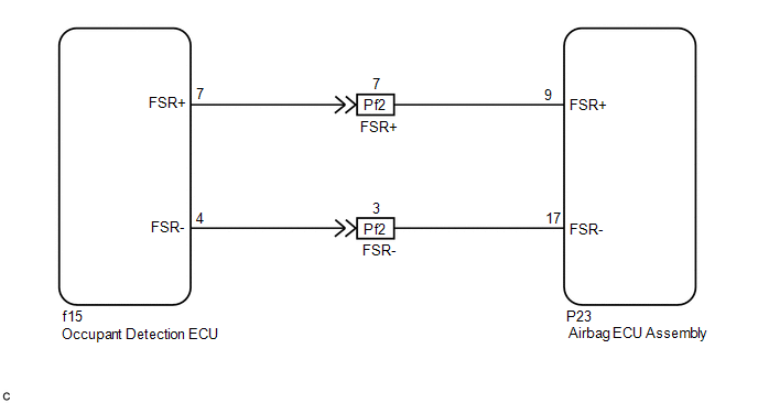
The occupant classification system circuit consists of the airbag ECU assembly and occupant detection ECU.
If the airbag ECU assembly receives signals from the occupant detection ECU, it determines whether the instrument panel passenger airbag, front seat airbag RH and front seat outer belt assembly should be operated.
DTC B1650 is stored when a malfunction is detected in the occupant classification system circuit.
| DTC No. | Detection Item | DTC Detection Condition | Trouble Area |
|---|---|---|---|
| B1650 | Occupant Classification System Malfunction | One of the following conditions is met:
|
|
WIRING DIAGRAM
CAUTION / NOTICE / HINT
NOTICE:
-
After the power switch is turned off, there may be a waiting time before disconnecting the negative (-) auxiliary battery terminal.
Click here
.gif)
-
When disconnecting and reconnecting the auxiliary battery
Click here
HINT:
When disconnecting and reconnecting the auxiliary battery, there is an automatic learning function that completes learning when the respective system is used.
Click here
-
After replacing the airbag ECU assembly, refer to initialization.
Click here
PROCEDURE
| 1. | CHECK DTC |
(a) Turn the power switch on (IG), and wait for at least 60 seconds.
(b) Clear the DTCs.
Click here
HINT:
- First clear the DTCs stored in the occupant detection ECU, and then clear the DTCs stored in the airbag ECU assembly.
- Use the Techstream to clear the DTCs of the occupant detection ECU, otherwise the DTCs cannot be cleared.
(c) Turn the power switch off.
(d) Turn the power switch on (IG), and wait for at least 60 seconds.
(e) Check for DTCs of the occupant detection ECU.
Click here
| DTC is output | .gif) | GO TO OCCUPANT CLASSIFICATION SYSTEM |
|
.gif)
| 2. | CHECK DTC |
(a) Clear the DTCs.
Click here
(b) Turn the power switch off.
(c) Turn the power switch on (IG), and wait for at least 60 seconds.
(d) Check for DTCs.
Click here
HINT:
Codes other than DTC B1650 may be output at this time, but they are not related to this check.
| DTC B1650 is not output | | USE SIMULATION METHOD TO CHECK |
|
| 3. | CHECK CONNECTION OF CONNECTORS |
(a) Turn the power switch off.
(b) Disconnect the cable from the negative (-) auxiliary battery terminal, and wait for at least 90 seconds.
(c) Check that the connectors are properly connected to the airbag ECU assembly and occupant detection ECU.
| Connectors are not properly connected | | CONNECT CONNECTORS PROPERLY |
|
| 4. | CHECK CONNECTORS |
| (a) Disconnect the connectors from the airbag ECU assembly and occupant detection ECU. |
|
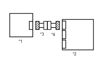
(b) Check that the connectors (on the airbag ECU assembly side and occupant detection ECU side) are not damaged.
| Connectors are deformed or damaged | | REPLACE FRONT SEAT WIRE RH OR FLOOR WIRE |
|
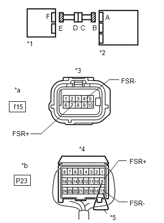
| 5. | CHECK OCCUPANT DETECTION ECU CIRCUIT |
| (a) Connect the cable to the negative (-) auxiliary battery terminal, and wait for at least 2 seconds. |
|
(b) Turn the power switch on (IG).
(c) Measure the voltage according to the value(s) in the table below.
Standard Voltage:
| Tester Connection | Switch Condition | Specified Condition |
|---|---|---|
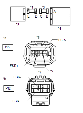
| f15-7 (FSR+) - Body ground | Power switch on (IG) | Below 1 V |
| f15-4 (FSR-) - Body ground | Power switch on (IG) | Below 1 V |
(d) Turn the power switch off.
(e) Disconnect the cable from the negative (-) auxiliary battery terminal, and wait for at least 90 seconds.
(f) Using a service wire, connect terminals 9 (FSR+) and 17 (FSR-) of connector B.
NOTICE:
Do not forcibly insert the service wire into the terminals of the connector.
(g) Measure the resistance according to the value(s) in the table below.
Standard Resistance:
| Tester Connection | Condition | Specified Condition |
|---|---|---|
| f15-7 (FSR+) - f15-4 (FSR-) | Always | Below 1 Ω |
(h) Disconnect the service wire from connector B.
(i) Measure the resistance according to the value(s) in the table below.
Standard Resistance:
| Tester Connection | Condition | Specified Condition |
|---|---|---|
| f15-7 (FSR+) - f15-4 (FSR-) | Always | 1 MΩ or higher |
| f15-7 (FSR+) - Body ground | Always | 1 MΩ or higher |
| f15-4 (FSR-) - Body ground | Always | 1 MΩ or higher |
| NG | | GO TO STEP 7 |
|
| 6. | CHECK DTC |
| (a) Connect the connectors to the airbag ECU assembly and occupant detection ECU. |
|
(b) Connect the cable to the negative (-) auxiliary battery terminal, and wait for at least 2 seconds.
(c) Turn the power switch on (IG), and wait for at least 60 seconds.
(d) Clear the DTCs.
Click here
(e) Turn the power switch off.
(f) Turn the power switch on (IG), and wait for at least 60 seconds.
(g) Check for DTCs.
Click here
HINT:
Codes other than DTC B1650 may be output at this time, but they are not related to this check.
| DTC B1650 is output | | REPLACE AIRBAG ECU ASSEMBLY |
| DTC B1650 is not output | | USE SIMULATION METHOD TO CHECK |
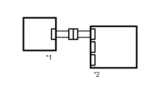
| 7. | CHECK FRONT SEAT WIRE RH |
| (a) Disconnect the front seat wire RH connector from the floor wire. |
|
(b) Connect the cable to the negative (-) auxiliary battery terminal, and wait for at least 2 seconds.
(c) Turn the power switch on (IG).
(d) Measure the voltage according to the value(s) in the table below.
Standard Voltage:
| Tester Connection | Switch Condition | Specified Condition |
|---|---|---|
| Pf2-7 (FSR+) - Body ground | Power switch on (IG) | Below 1 V |
| Pf2-3 (FSR-) - Body ground | Power switch on (IG) | Below 1 V |
(e) Turn the power switch off.
(f) Disconnect the cable from the negative (-) auxiliary battery terminal, and wait for at least 90 seconds.
(g) Using a service wire, connect terminals 7 (FSR+) and 4 (FSR-) of connector E.
NOTICE:
Do not forcibly insert the service wire into the terminals of the connector.
(h) Measure the resistance according to the value(s) in the table below.
Standard Resistance:
| Tester Connection | Condition | Specified Condition |
|---|---|---|
| Pf2-7 (FSR+) - Pf2-3 (FSR-) | Always | Below 1 Ω |
(i) Disconnect the service wire from connector E.
(j) Measure the resistance according to the value(s) in the table below.
Standard Resistance:
| Tester Connection | Condition | Specified Condition |
|---|---|---|
| Pf2-7 (FSR+) - Pf2-3 (FSR-) | Always | 1 MΩ or higher |
| Pf2-7 (FSR+) - Body ground | Always | 1 MΩ or higher |
| Pf2-3 (FSR-) - Body ground | Always | 1 MΩ or higher |
| OK | | REPLACE FLOOR WIRE |
| NG | | REPLACE FRONT SEAT WIRE RH |
READ NEXT:
 Driver Side Seat Position Sensor (B1653)
DESCRIPTION The seat position airbag sensor circuit consists of the airbag ECU assembly and seat position airbag sensor. DTC B1653 is stored when a malfunction is detected in the seat position airbag
Seat Belt Buckle Switch (LH) (B1656)
DESCRIPTION The seat belt buckle switch LH circuit consists of the airbag ECU assembly and front seat inner belt assembly LH. DTC B1656 is stored when a malfunction is detected in the seat belt buckle
P Seat Airbag Active Mode Indicator (B1660)
DESCRIPTION The passenger airbag ON/OFF indicator circuit consists of the airbag ECU assembly and passenger airbag ON/OFF indicator. The passenger airbag ON/OFF indicator indicates the operation condi
SEE MORE:
Installation
INSTALLATION CAUTION / NOTICE / HINT NOTICE: While the battery is connected, even if the power switch is off, the brake control system activates when the brake pedal is depressed or any door courtesy switch is turned on. Therefore, when servicing the brake system components, do not depress the brake
Open Circuit in Power Source Circuit (C13A0,C13A5,C13B0)
DESCRIPTION DTC No. Detection Item DTC Detection Condition Trouble Area Memory Note C13A0 Open Circuit in Power Source Circuit Both of following conditions are met:
Power switch on (IG) or electric parking brake switch (integration control and panel assembly) pulled to lock s
