Lexus NX: On-vehicle Inspection
ON-VEHICLE INSPECTION
PROCEDURE
1. CHECK AUXILIARY BATTERY
(a) Check that the auxiliary battery cables are connected to the correct terminals.
HINT:
If they are not, connect them properly.
(b) Check the auxiliary battery for damage and deformation.
HINT:
If severe damage, deformation or leakage is found, replace the auxiliary battery.
2. CHECK AUXILIARY BATTERY ELECTROLYTE VOLUME
(a) Check the volume of the electrolytes in each cell.
Standard electrolyte level:
Middle of upper line and lower line
If the electrolyte level is below the middle, replace the auxiliary battery.
3. CHECK AUXILIARY BATTERY VOLTAGE
(a) Turn the power switch off and turn on the high beam headlights for 30 seconds. This will remove the surface charge from the auxiliary battery.
(b) Measure the auxiliary battery voltage according to the value(s) in the table below.
| Tester Connection | Condition | Specified Condition | Result |
|---|---|---|---|
| Positive (+) auxiliary battery terminal - Negative (-) auxiliary battery terminal | 20°C (68°F), power switch off | 12.5 V or higher | Auxiliary battery is OK |
| 11.0 to 12.5 V | Recharge auxiliary battery | ||
| Below 11.0 V | Replace auxiliary battery |
4. RECHARGE AUXILIARY BATTERY
(a) Recharge the auxiliary battery.
HINT:
- Recharge the auxiliary battery according to the charger's instructions.
- Apply the appropriate charging current according to the type of auxiliary battery shown in the table below.
| Auxiliary Battery Type | Charging Current |
|---|---|
| LN2 | 5 A or less |
(b) Turn the power switch off and turn on the high beam headlights for 30 seconds. This will remove the surface charge from the auxiliary battery.
(c) Measure the auxiliary battery voltage according to the value(s) in the table below.
| Tester Connection | Condition | Specified Condition | Result |
|---|---|---|---|
| Positive (+) auxiliary battery terminal - Negative (-) auxiliary battery terminal | 20°C (68°F), power switch off | 12.5 V or higher | Auxiliary battery is OK |
| 11.0 to 12.5 V | Recharge auxiliary battery | ||
| Below 11.0 V | Replace auxiliary battery |
5. CHECK AUXILIARY BATTERY TERMINAL, FUSIBLE LINK AND FUSE
(a) Check that the auxiliary battery terminals are not loose or corroded.
Torque:
Positive (+) auxiliary battery terminal :
5.4 N·m {55 kgf·cm, 48 in·lbf}
Negative (-) auxiliary battery terminal :
5.4 N·m {55 kgf·cm, 48 in·lbf}
If the terminals are corroded, clean them.
(b) Measure the resistance of each fusible link and fuse for the auxiliary battery charging system.
Standard Resistance:
Below 1 Ω
If any of the results is not as specified, replace the fusible link or fuse as necessary.
6. CHECK AMD TERMINAL
CAUTION:
Be sure to wear insulated gloves.
(a) Check that the service plug grip is not installed.
NOTICE:
After removing the service plug grip, do not turn the power switch on (READY), unless instructed by the repair manual because this may cause a malfunction.
(b) Check that the AMD terminal is connected securely, and there is no contact problem.
If there are any arc marks, replace the affected parts.
(c) Check that the nut for the AMD terminal is tightened to the specified torque.
HINT:
If there are no arc marks and the AMD terminal connection is faulty, connect the AMD terminal securely.
(d) Install the service plug grip.
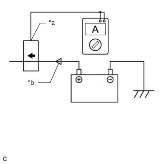
7. CHECK DC/DC CONVERTER FUNCTION
| (a) Connect the AC/DC 400 A probe to the positive (+) auxiliary battery cable. |
|
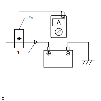
(b) Turn the power switch on (READY) and leave the vehicle as it is until the electric current flowing into the auxiliary battery becomes 10 A or less.
(c) With the power switch on (READY), set the headlight position switch and blower motor switch to the HI position, and then turn the rear window defogger on.
| (d) Measure the current and voltage according to the value(s) in the table below. Result:
If the result is not as specified, replace the inverter with converter assembly. |
|
READ NEXT:
 Precaution
PRECAUTION CAN COMMUNICATION SYSTEM TROUBLESHOOTING (a) Because the order of diagnosis is important to allow correct diagnosis, make sure to begin troubleshooting using How to Proceed with Troubleshoo
SEE MORE:
Removal
REMOVAL PROCEDURE 1. REMOVE DOOR SCUFF PLATE ASSEMBLY LH Click here 2. REMOVE COWL SIDE TRIM BOARD LH Click here 3. REMOVE INSTRUMENT SIDE PANEL LH Click here 4. REMOVE NO. 1 INSTRUMENT PANEL SAFETY PAD SUB-ASSEMBLY Click here 5. REMOVE REAR CONSOLE ARMREST ASSEMBLY Click here
Diagnostic Trouble Code Chart
DIAGNOSTIC TROUBLE CODE CHART Telematics System DTC No. Detection Item Link U014087 Lost Communication with Body Control Module Missing Message U015587 Lost Communication with Instrument Panel Cluster (IPC) Control Module Missing Message U016387 Lost Communication
