Lexus NX: Precaution
PRECAUTION
CAN COMMUNICATION SYSTEM TROUBLESHOOTING
(a) Because the order of diagnosis is important to allow correct diagnosis, make sure to begin troubleshooting using How to Proceed with Troubleshooting when CAN communication system related DTCs are output.
Click here .gif)
(b) Precaution for steering system handling
(1) Be careful when replacing parts. Incorrect replacement could affect the performance of the steering system and result in hazardous driving.
for Power Title and Power Telescopic Steering Colum: Click here
for Manual Tilt and Manual Telescopic Steering Column: Click here
(c) Precaution for SRS airbag system handling
NOTICE:
This vehicle is equipped with a supplemental restraint system (SRS) which includes parts such as airbags for the driver and passenger. Failure to carry out service operations in the correct sequence could cause unexpected SRS deployment during servicing and may cause a serious accident. Before servicing (including removal or installation of parts, inspection or replacement), be sure to read precaution for SRS airbag system.
Click here
(d) Precaution for when disconnecting a wire harness from a CAN junction connector
(1) When disconnecting a wire harness from a CAN junction connector, use tape or tags to identify each connector and make sure to reconnect each connector to its original location on the CAN junction connector.
HINT:
- Reconnecting a connector to a location other than its original location on the CAN junction connector will not affect system performance. However, reconnecting connectors to their original locations makes future maintenance easier and avoids negative effects on wire harnesses, such as excessive tension.
-
For information on how to identify the ECUs or sensors connected to the CAN junction connector, refer to Terminals of ECU.
Click here
(e) Bus line repair
(1) After repairing a bus line with solder, wrap the repaired area with electrical tape.
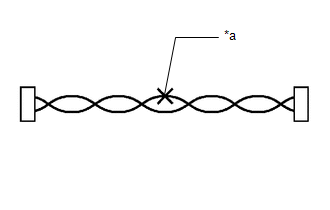
| *a | Soldered Area to Be Wrapped with Electrical Tape |
NOTICE:
- When installing, make sure that these lines are twisted, because CAN bus lines are likely to be influenced by electrical noise if the bus lines are not twisted.
- Ensure that there is no gap between the CANH wire and CANL wire.
- Make sure that the distance between the first twist of the wires and the connector is less than 80 mm (3.15 in).
- When repairing the CAN bus lines, do not change the length of the lines. (Make sure that the length of the CANH bus line and CANL bus line are the same.)
(2) Do not use bypass wiring between connectors.
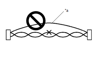
| *a | Bypass Wire |
NOTICE:
- The ability of the twisted bus lines to resist interference will be lost if bypass wiring is used.
- Do not use a twisted pair of wires for bypass wiring.
(f) Connector handling
(1) When checking resistance with a tester, insert the tester probes from the backside (harness side) of the connector.
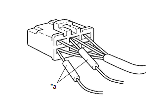
| *a | Tester Probe |
(2) When it is not possible to insert the tester from the backside of the connector, using service wires, measure from the front side of the connector.
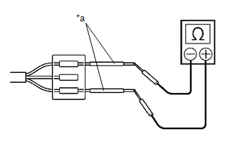
| *a | Service Wire |
(g) Precaution for when replacing a gateway function equipped ECU (sub bus monitoring ECU)
(1) When replacing a gateway equipped function ECU (sub bus monitoring ECU) with one which was installed to another vehicle, perform initialization of the sub bus monitoring ECU in order to clear stored bus information.
Click here
NOTICE:
If the stored bus information does not match the current sub bus configuration, DTCs may be stored and fail-safe functions may operate.
HINT:
It is not necessary to perform initialization of a gateway monitoring ECU (sub bus monitoring ECU) when using a sub bus monitoring ECU which was installed to another vehicle with the same sub bus configuration.
(h) Precautions for when a gateway function equipped ECU (sub bus monitor ECU) detects communication DTCs for ECUs not connected to the ECU
(1) Refer to precautions when replacing a gateway function equipped ECU (sub bus monitoring ECU) and initialize the connection information of the ECU.
(2) Clear the DTCs and check that no DTCs are output.
(i) Difference between a pre-installed LEXUS genuine navigation receiver and a CAN compatible optional navigation receiver
(1) Some navigation receivers are available as CAN compatible optional devices. Be aware that CAN compatible optional devices do not have the same diagnostic features or characteristics of pre-installed LEXUS genuine navigation receivers.
NOTICE:
- CAN compatible optional navigation receivers receive data from the CAN communication system. However, most CAN compatible optional navigation receivers do not send signals to the CAN bus main line.
- Most CAN compatible optional navigation receivers will not be displayed on the "Communication Bus Check" screen of the Techstream.
- When checking for DTCs using the Techstream, DTCs for CAN compatible optional navigation receivers will not be displayed on the Techstream.
READ NEXT:
 Parts Location
PARTS LOCATION ILLUSTRATION *A w/ Memory *B w/ Pre-collision System *C for Triple Beam Headlight - - *1 FORWARD RECOGNITION CAMERA *2 OUTER MIRROR CONTROL ECU ASSEMBLY RH
System Diagram
SYSTEM DIAGRAM SYSTEM DIAGRAM (a) The CAN communication system is composed of 5 buses. CAN Main Bus Line Terminating Resistor CAN Branch Line * Gateway Function Equipped ECU
System Description
SYSTEM DESCRIPTION BRIEF DESCRIPTION (a) The Controller Area Network (CAN) is a serial data communication system for real time application. It is a vehicle multiplex communication system which has a h
SEE MORE:
On-vehicle Inspection
ON-VEHICLE INSPECTION PROCEDURE 1. INSPECT COOLING FAN MOTOR (a) Disconnect the cooling fan motor connector. (b) Check that the fan rotates smoothly by hand. (c) Check that the cooling fan motor turns smoothly when the battery is connected to the cooling fan motor connector. Click here
Steering Angle Sensor Communication Error (C1784)
DESCRIPTION Steering sensor signals are sent to the absorber control ECU via CAN communication. When there is a communication malfunction, the malfunction will be detected by the diagnosis function. DTC No. Detection Item DTC Detection Condition Trouble Area Warning Indicate C1784 S
