Lexus NX: Engine Hood Courtesy Switch
Components
COMPONENTS
ILLUSTRATION
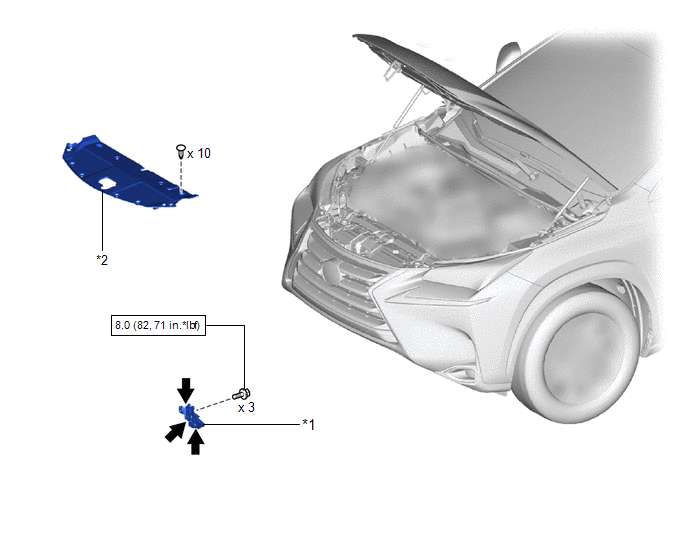
| *1 | HOOD LOCK ASSEMBLY (ENGINE HOOD COURTESY SWITCH) | *2 | RADIATOR SUPPORT OPENING COVER |
.png) | N*m (kgf*cm, ft.*lbf) : Specified torque | .png) | MP grease |
Removal
REMOVAL
PROCEDURE
1. REMOVE RADIATOR SUPPORT OPENING COVER
Click here .gif)
2. REMOVE HOOD LOCK ASSEMBLY (ENGINE HOOD COURTESY SWITCH)
| (a) Disconnect the connector. |
|
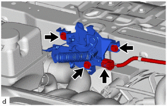
(b) Remove the 3 bolts.
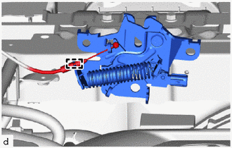
| (c) Detach the guide, disconnect the hood lock control cable and remove the hood lock assembly (engine hood courtesy switch). |
|
Inspection
INSPECTION
PROCEDURE
1. INSPECT HOOD LOCK ASSEMBLY (ENGINE HOOD COURTESY SWITCH)
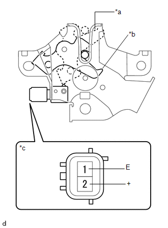
| (a) Measure the resistance according to the value(s) in the table below. Standard Resistance:
If the result is not as specified, replace the hood lock assembly (engine hood courtesy switch). |
|
Installation
INSTALLATION
PROCEDURE
1. INSTALL HOOD LOCK ASSEMBLY (ENGINE HOOD COURTESY SWITCH)
(a) Apply MP grease to the sliding areas of the lock.
(b) Attach the guide and connect the hood lock control cable.
(c) Install the hood lock assembly (engine hood courtesy switch) with the 3 bolts.
Torque:
8.0 N·m {82 kgf·cm, 71 in·lbf}
(d) Connect the connector.
2. INSTALL RADIATOR SUPPORT OPENING COVER
Click here .gif)
3. ADJUST HOOD SUB-ASSEMBLY
Click here
READ NEXT:
 Id Code Box
ComponentsCOMPONENTS ILLUSTRATION *1 AIR CONDITIONER UNIT ASSEMBLY *2 ID CODE BOX (IMMOBILIZER CODE ECU) InstallationINSTALLATION PROCEDURE 1. INSTALL ID CODE BOX (IMMOBILIZER CODE ECU)
Precaution
PRECAUTION PRECAUTION FOR DISCONNECTING CABLE FROM NEGATIVE AUXILIARY BATTERY TERMINAL NOTICE:
After the power switch is turned off, there may be a waiting time before disconnecting the negative (-
SEE MORE:
System Description
SYSTEM DESCRIPTION HEADUP DISPLAY SYSTEM DESCRIPTION HINT:
The meter mirror sub-assembly receives signals from the combination meter assembly via the CAN communication line. Information is displayed on the front window based on received signals.
The meter mirror sub-assembly receives navigation
XM Tuner Antenna Disconnected (B15FE,B15FF)
DESCRIPTION These DTCs are stored when a malfunction occurs in the roof antenna assembly which is connected to the radio receiver assembly. DTC No. Detection Item DTC Detection Condition Trouble Area B15FE XM Tuner Antenna Disconnected The roof antenna assembly is not connected.
