Lexus NX: Luggage Compartment Room Light
Components
COMPONENTS
ILLUSTRATION
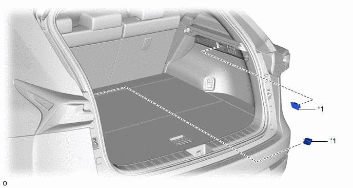
| *1 | NO. 1 LUGGAGE COMPARTMENT LIGHT ASSEMBLY | - | - |
Removal
REMOVAL
PROCEDURE
1. REMOVE NO. 1 LUGGAGE COMPARTMENT LIGHT ASSEMBLY (for LH Side)
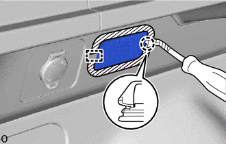
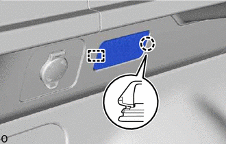
(a) Put protective tape around the No. 1 luggage compartment light assembly.
.png) | Protective Tape |
(b) Using a clip remover, detach the claw and guide.
HINT:
Tape the clip remover tip before use.
(c) Disconnect the connector and remove the No. 1 luggage compartment light assembly.
2. REMOVE NO. 1 LUGGAGE COMPARTMENT LIGHT ASSEMBLY (for RH Side)
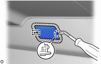
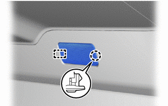
(a) Put protective tape around the No. 1 luggage compartment light assembly.
| | Protective Tape |
(b) Using a clip remover, detach the claw and guide.
HINT:
Tape the clip remover tip before use.
(c) Disconnect the connector and remove the No. 1 luggage compartment light assembly.
Inspection
INSPECTION
PROCEDURE
1. INSPECT NO. 1 LUGGAGE COMPARTMENT LIGHT ASSEMBLY (for LH Side)
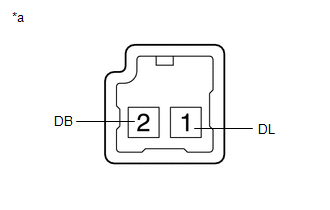
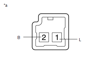
| (a) Inspect the No. 1 luggage compartment light assembly. (1) Apply auxiliary battery voltage to the connector and check the light illumination condition. OK:
If the result is not as specified, replace the No. 1 luggage compartment light assembly. |
|
2. INSPECT NO. 1 LUGGAGE COMPARTMENT LIGHT ASSEMBLY (for RH Side)
| (a) Inspect the No. 1 luggage compartment light assembly. (1) Apply auxiliary battery voltage to the connector and check the light illumination condition. OK:
If the result is not as specified, replace the No. 1 luggage compartment light assembly. |
|
Installation
INSTALLATION
PROCEDURE
1. INSTALL NO. 1 LUGGAGE COMPARTMENT LIGHT ASSEMBLY (for LH Side)
| (a) Connect the connector. |
|
(b) Attach the guide and claw to install the No. 1 luggage compartment light assembly.
2. INSTALL NO. 1 LUGGAGE COMPARTMENT LIGHT ASSEMBLY (for RH Side)
| (a) Connect the connector. |
|
(b) Attach the guide and claw to install the No. 1 luggage compartment light assembly.
READ NEXT:
 Components
COMPONENTS ILLUSTRATION *1 MAP LIGHT ASSEMBLY (PERSONAL LIGHT) *2 MAP LIGHT SUB-ASSEMBLY
Removal
REMOVAL PROCEDURE 1. REMOVE MAP LIGHT ASSEMBLY (PERSONAL LIGHT) (a) Using moulding remover D, detach the 4 clips. (b) Disconnect the connectors and remove the map light assembly (person
SEE MORE:
Certification Ecu
ComponentsCOMPONENTS ILLUSTRATION *1 CERTIFICATION ECU (SMART KEY ECU ASSEMBLY) *2 ECU INTEGRATION BOX RH *3 GLOVE COMPARTMENT DOOR ASSEMBLY *4 NO. 2 INSTRUMENT PANEL UNDER COVER SUB-ASSEMBLY N*m (kgf*cm, ft.*lbf): Specified torque - - RemovalREMOVAL PROCEDURE 1.
Removal
REMOVAL CAUTION / NOTICE / HINT NOTICE:
When the brake pedal is first depressed after replacing the brake pads or pushing back the disc brake piston, DTC C1214 may be output. As there is no malfunction, clear the DTC.
While the auxiliary battery is connected, even if the power switch is off, th
