Lexus NX: Inspection
INSPECTION
PROCEDURE
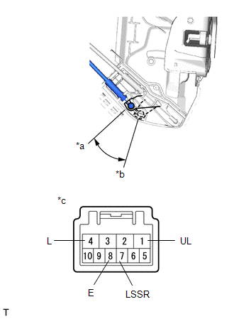
1. INSPECT FRONT DOOR LOCK ASSEMBLY LH
| (a) Check the door lock motor operation. (1) Apply auxiliary battery voltage to the motor connector and check the operation of the door lock motor. OK:
If the result is not as specified, replace the front door lock assembly LH. |
|
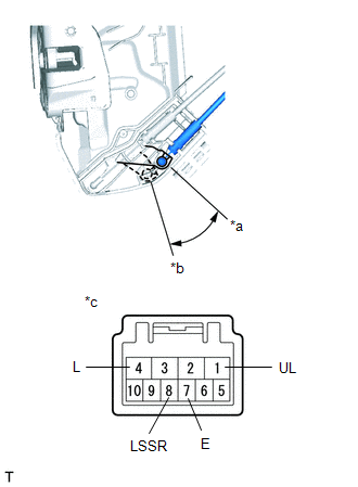
(b) Check the operation of the door unlock detection switch.
(1) Measure the resistance according to the value(s) in the table below.
Standard Resistance:
| Tester Connection | Condition | Specified Condition |
|---|---|---|
| 7 (E) - 8 (LSSR) | Lock | 10 kΩ or higher |
| Unlock | Below 1 Ω |
If the result is not as specified, replace the front door lock assembly LH.
| (c) Check the resistance of the lock and unlock switch. (1) Measure the resistance according to the value(s) in the table below. Standard Resistance:
If the result is not as specified, replace the front door lock assembly LH. |
|
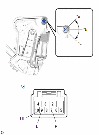
2. INSPECT FRONT DOOR LOCK ASSEMBLY RH
| (a) Check the door lock motor operation. (1) Apply auxiliary battery voltage to the motor connector and check the operation of the door lock motor. OK:
If the result is not as specified, replace the front door lock assembly RH. |
|
(b) Check the operation of the door unlock detection switch.
(1) Measure the resistance according to the value(s) in the table below.
Standard Resistance:
| Tester Connection | Condition | Specified Condition |
|---|---|---|
| 7 (LSSR) - 8 (E) | Lock | 10 kΩ or higher |
| 7 (LSSR) - 8 (E) | Unlock | Below 1 Ω |
If the result is not as specified, replace the front door lock assembly RH.
READ NEXT:
 Installation
INSTALLATION CAUTION / NOTICE / HINT HINT:
Use the same procedure for the RH and LH sides.
The procedure listed below is for the LH side.
A bolt without a torque specification is shown in the s
Precaution
PRECAUTION PRECAUTIONS WHEN USING TECHSTREAM (a) When using the Techstream with the vehicle power switch off, connect the Techstream to the DLC3 and turn a courtesy light switch on and off at interval
SEE MORE:
Problem Symptoms Table
PROBLEM SYMPTOMS TABLE HINT:
Use the table below to help determine the cause of problem symptoms. If multiple suspected areas are listed, the potential causes of the symptoms are listed in order of probability in the "Suspected Area" column of the table. Check each symptom by checking the suspect
Front Radar Sensor Optical Axis Misalignment Malfunction (C1A1100)
DESCRIPTION The millimeter wave radar sensor assembly performs self-diagnosis to check for misalignment of its beam axis. If misalignment is detected, the millimeter wave radar sensor assembly stores DTC C1A1100. DTC No. Detection Item DTC Detection Condition Trouble Area C1A1100 Fron
