Lexus NX: Parts Location
PARTS LOCATION
ILLUSTRATION
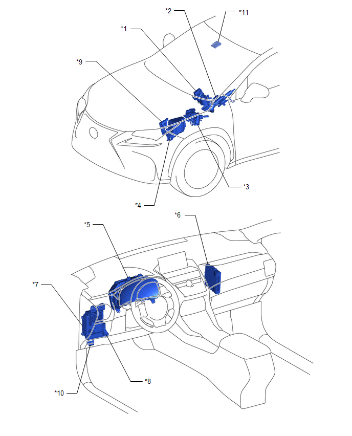
| *1 | POWER STEERING ECU ASSEMBLY | *2 | ELECTRIC POWER STEERING COLUMN SUB-ASSEMBLY - POWER STEERING MOTOR ASSEMBLY - MOTOR ROTATION ANGLE SENSOR - TORQUE SENSOR - ECU WIRE SUB-ASSEMBLY |
| *3 | SKID CONTROL ECU (BRAKE BOOSTER WITH MASTER CYLINDER ASSEMBLY) | *4 | NO. 1 ENGINE ROOM RELAY BLOCK - EPS FUSE |
| *5 | COMBINATION METER ASSEMBLY - POWER STEERING WARNING LIGHT | *6 | HYBRID VEHICLE CONTROL ECU |
| *7 | MAIN BODY ECU (MULTIPLEX NETWORK BODY ECU) | *8 | INSTRUMENT PANEL JUNCTION BLOCK ASSEMBLY - EPS-IG FUSE |
| *9 | ECM | *10 | DLC3 |
| *11 | FORWARD RECOGNITION CAMERA | - | - |
READ NEXT:
 System Diagram
SYSTEM DIAGRAM
System Description
SYSTEM DESCRIPTION
The power steering system generates torque through the operation of the motor and the reduction gear installed on the column shaft in order to assist steering effort.
The power
How To Proceed With Troubleshooting
CAUTION / NOTICE / HINT HINT:
Use these procedures to troubleshoot the power steering system.
*: Use the Techstream.
PROCEDURE 1. VEHICLE BROUGHT TO WORKSHOP
NEXT
SEE MORE:
How To Proceed With Troubleshooting
CAUTION / NOTICE / HINT HINT:
Use the following procedure to troubleshoot the vehicle proximity notification system.
*: Use the GTS.
PROCEDURE 1. VEHICLE BROUGHT TO WORKSHOP
NEXT 2. CUSTOMER PROBLEM ANALYSIS AND SYMPTOM CHECK HINT:
In troubleshooting, co
Reassembly
REASSEMBLY CAUTION / NOTICE / HINT HINT:
Use the same procedure for the RH and LH sides.
The following procedure is for the LH side.
PROCEDURE 1. TEMPORARILY INSTALL FRONT DISC BRAKE BLEEDER PLUG (a) Temporarily install the front disc brake bleeder plug to the disc brake cylinder assembly LH
© 2016-2026 Copyright www.lexunx.com
