Lexus NX: Inspection
INSPECTION
PROCEDURE
1. INSPECT HV BATTERY JUNCTION BLOCK ASSEMBLY
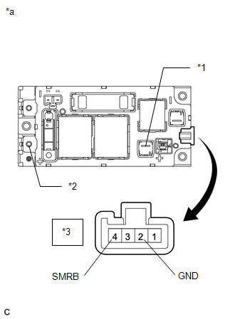
| (a) Inspect SMRB: (1) Measure the resistance according to the value(s) in the table below. Standard Resistance:
(2) Measure the resistance according to the value(s) in the table below. Standard Resistance:
If the result is not as specified, replace the hybrid battery junction block assembly. |
|
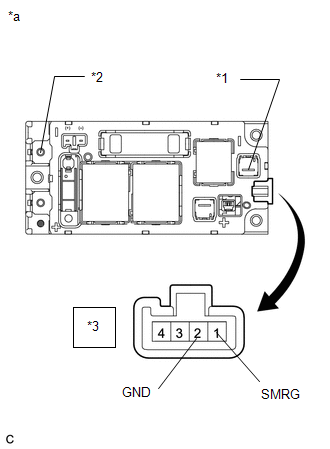
| (b) Inspect SMRG: (1) Measure the resistance according to the value(s) in the table below. Standard Resistance:
(2) Measure the resistance according to the value(s) in the table below. Standard Resistance:
If the result is not as specified, replace the hybrid battery junction block assembly. |
|
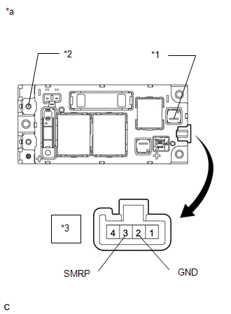
| (c) Inspect SMRP: (1) Measure the resistance according to the value(s) in the table below. Standard Resistance:
(2) Measure the resistance according to the value(s) in the table below. Standard Resistance:
If the result is not as specified, replace the hybrid battery junction block assembly. |
|
READ NEXT:
 Installation
INSTALLATION PROCEDURE 1. INSTALL HV BATTERY JUNCTION BLOCK ASSEMBLY CAUTION: Wear insulated gloves and use insulated tools. (a) Install the hybrid battery junction block assembly with the 3 nuts. Tor
Dtc Check / Clear
DTC CHECK / CLEAR CHECK FOR DTCS (a) Connect the Techstream to the DLC3. (b) Turn the power switch on (IG). (c) Turn the Techstream on. (d) Enter the following menus: Powertrain / Hybrid Control / Tro
SEE MORE:
System Description
SYSTEM DESCRIPTION FUNCTION DESCRIPTION (a) Electronically Controlled Brake System (1) Upon receiving signals from the skid control ECU (brake booster with master cylinder assembly), this system effects hydraulic pressure control at the 4 wheels. (b) Regenerative Brake Cooperative Control (1) Contro
Components
COMPONENTS ILLUSTRATION *1 CENTER EXHAUST PIPE ASSEMBLY *2 EXHAUST PIPE DAMPER *3 FRONT EXHAUST PIPE ASSEMBLY *4 HEATED OXYGEN SENSOR *5 TAIL EXHAUST PIPE ASSEMBLY *6 EXHAUST PIPE SUPPORT *7 COMPRESSION SPRING *8 GASKET N*m (kgf*cm, ft.*lbf): Specified
