Lexus NX: Installation
INSTALLATION
CAUTION / NOTICE / HINT
NOTICE:
- When replacing with a new inverter with converter assembly, securely lock the retainer of the inverter cooling hose since it is not locked.
- Before replacing the wire harness boot, check if any DTCs are output.
HINT:
Remove the tape that was attached to the hose at removal in accordance with the installation procedure.
PROCEDURE
1. INSTALL NO. 3 ENGINE ROOM WIRE
(a) Install the No. 3 engine room wire with the nut.
Torque:
18 N·m {184 kgf·cm, 13 ft·lbf}
NOTICE:
Temporarily install the nut by hand, then tighten using a tool.
(b) Close the terminal cap.
2. INSTALL NO. 2 INVERTER RESERVE TANK BRACKET
(a) Install the No. 2 inverter reserve tank bracket to the inverter with converter assembly with the 2 bolts.
Torque:
10 N·m {102 kgf·cm, 7 ft·lbf}
3. INSTALL HYBRID INVERTER PROTECTOR ASSEMBLY
(a) Install the hybrid inverter protector assembly to the inverter with converter assembly with the 2 bolts.
Torque:
10 N·m {102 kgf·cm, 7 ft·lbf}
4. INSTALL WIRE HARNESS CLAMP BRACKET
(a) Install the wire harness clamp bracket to the inverter with converter assembly with the bolt.
Torque:
7.7 N·m {79 kgf·cm, 68 in·lbf}
5. INSTALL NO. 3 INVERTER BRACKET
| (a) Temporarily install the No. 3 inverter bracket to the inverter with converter assembly with the 2 bolts. HINT: When installing, align with the stopper. |
|
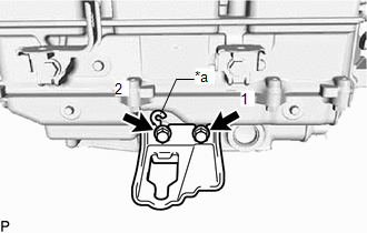
(b) Tighten the 2 bolts in the sequence shown in the illustration.
Torque:
3.5 N·m {36 kgf·cm, 31 in·lbf}
6. INSTALL NO. 2 INVERTER BRACKET
| (a) Temporarily install the No. 2 inverter bracket to the inverter with converter assembly with the 2 bolts. HINT: When installing, align with the stopper. |
|
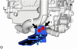
(b) Tighten the 2 bolts in the sequence shown in the illustration.
Torque:
3.5 N·m {36 kgf·cm, 31 in·lbf}
7. INSTALL NO. 4 INVERTER BRACKET
| (a) Temporarily install the No. 4 inverter bracket to the inverter with converter assembly with the 2 bolts. HINT: When installing, align with the stopper. |
|
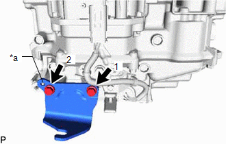
(b) Tighten the 2 bolts in the sequence shown in the illustration.
Torque:
3.5 N·m {36 kgf·cm, 31 in·lbf}
8. INSTALL AIR CLEANER BRACKET
(a) Install the air cleaner bracket to the inverter with converter assembly with the bolt.
Torque:
5.0 N·m {51 kgf·cm, 44 in·lbf}
9. INSTALL NO. 1 AIR CLEANER BRACKET
(a) Install the No. 1 air cleaner bracket to the inverter with converter assembly with the bolt.
Torque:
5.0 N·m {51 kgf·cm, 44 in·lbf}
10. INSTALL HIGH VOLTAGE FUSE
CAUTION:
Be sure to wear insulated gloves.
HINT:
Perform this procedure only when replacement of the high voltage fuse is necessary.
| (a) Remove the bolt and connector cover assembly. NOTICE:
|
|
.png)
(b) Install the high voltage fuse with 2 new nuts.
Torque:
4.0 N·m {41 kgf·cm, 35 in·lbf}
NOTICE:
Be sure to use a torque wrench to tighten the nuts.
(c) Temporarily install the connector cover assembly with the bolt to prevent any foreign objects or water from entering the inverter with converter assembly.
11. INSTALL INVERTER WITH CONVERTER ASSEMBLY
CAUTION:
Be sure to wear insulated gloves.
NOTICE:
- Since the inverter with converter assembly is very heavy, 2 people are needed to install it on the vehicle. Take care not to damage surrounding parts.
- To prevent damage, do not hold the connectors when lifting up the inverter with converter assembly.
- To prevent damage caused by static electricity, do not touch the terminals at the openings of disconnected connectors.
(a) Temporarily install the No. 6 inverter bracket with the 2 bolts.
(b) Temporarily install the inverter with converter assembly with the 2 nuts and bolt.
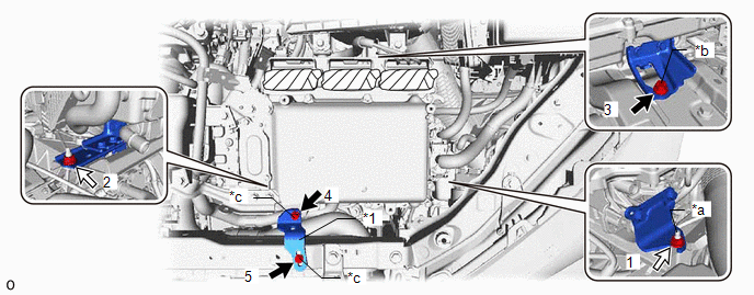
| *1 | No. 6 Inverter Bracket | - | - |
| *a | The stud bolt must firmly contact the inverter bracket stay. | *b | Bolt A |
| *c | Bolt B | - | - |
.png) | Bolt | .png) | Nut |
(c) Tighten the 2 nuts and 3 bolts in the order shown in the illustration.
Torque:
Bolt A :
13 N·m {133 kgf·cm, 10 ft·lbf}
Bolt B :
10.5 N·m {107 kgf·cm, 8 ft·lbf}
Nut :
13 N·m {133 kgf·cm, 10 ft·lbf}
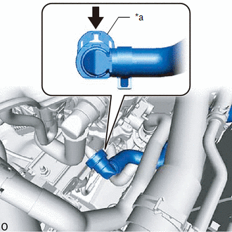
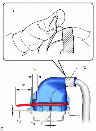
12. CONNECT NO. 2 INVERTER COOLING HOSE ASSEMBLY
| (a) Connect the No. 2 inverter cooling hose assembly, and slide the retainer as shown in the illustration to secure. NOTICE:
|
|
13. CONNECT NO. 3 ENGINE ROOM WIRE
| (a) Connect the 2 claws, and connect the No. 3 engine room wire to the junction block. |
|
.png)
(b) Connect the No. 3 engine room wire with the nut.
Torque:
8.4 N·m {86 kgf·cm, 74 in·lbf}
(c) Install the relay block cover.
14. CONNECT LOW VOLTAGE CONNECTOR
| (a) Connect the 3 low voltage connectors, and lock the connectors with the lock lever. NOTICE:
|
|
15. INSTALL INVERTER PROTECTOR
| (a) Install the inverter protector with the bolt. Torque: 8.0 N·m {82 kgf·cm, 71 in·lbf} HINT: When installing, align with the stopper. |
|
16. REMOVE CONNECTOR COVER ASSEMBLY
Click here .gif)
17. CONNECT NO. 2 FRAME WIRE
CAUTION:
Be sure to wear insulated gloves.
NOTICE:
- When connecting the No. 2 frame wire, do not damage the terminals, connector housing and inverter with converter assembly.
- Do not touch the connector rubber seal and terminal.
- Do not allow any foreign objects or water to enter the inverter with converter assembly.
- The connectors should be connected securely.
- The connectors must be securely locked.
| (a) Connect the No. 2 frame wire to the inverter with converter assembly with the clamp. |
|
.png)
(b) Secure the No. 2 frame wire to the inverter with converter assembly with the bolt.
Torque:
8.0 N·m {82 kgf·cm, 71 in·lbf}
18. CONNECT ENGINE WIRE
CAUTION:
Be sure to wear insulated gloves.
NOTICE:
- When connecting the engine wire, do not damage the terminals, connector housing and inverter with converter assembly.
- Do not touch the connector rubber seal and terminal.
- Do not allow any foreign objects or water to enter the inverter with converter assembly.
- The connectors should be connected securely.
- The connectors must be securely locked.
| (a) Connect the engine wire to the inverter with converter assembly. |
|
.png)
19. INSTALL CONNECTOR COVER ASSEMBLY
CAUTION:
Be sure to wear insulated gloves.
(a) Using an insulated tool, install the connector cover assembly with the 2 bolts.
Torque:
8.0 N·m {82 kgf·cm, 71 in·lbf}
NOTICE:
Make sure that the interlock is fully engaged.
20. INSTALL NO. 2 FRAME WIRE
CAUTION:
Be sure to wear insulated gloves.
NOTICE:
- When connecting the No. 2 frame wire, do not damage the terminals, connector housing and inverter with converter assembly.
- Do not touch the connector rubber seal and terminal.
- Do not allow any foreign objects or water to enter the inverter with converter assembly.
- Before replacing the wire harness boot, check if any DTCs are output.
| (a) Install new Tie Band to the wire harness boot as shown in the illustration. NOTICE: Use the Tie Band included with the part. HINT:
|
|
(b) After wrapping a new insulating tape around the wire 1 time, wrap insulating tape around the connector cover 3 or 4 times as shown in the illustration.
NOTICE:
Use the insulating tape included with the part.
HINT:
- Wrap areas where the wire is exposed with insulating tape.
- Apply insulating tape so that there are no gaps in the wire harness boot.
- Ensure that tape with a width of approximately 1.5 mm or more is used.
| (c) Connect the No. 2 frame wire (rear motor high-voltage cable side) to the air cleaner bracket, and secure with the clamp. |
|
.png)
| (d) Secure the No. 2 frame wire. |
|
.png)
(e) Attach the 2 clamps.
(f) Using an insulated tool, secure the No. 2 frame wire to the inverter with converter assembly with the 3 bolts.
Torque:
8.0 N·m {82 kgf·cm, 71 in·lbf}
NOTICE:
- Make sure that the terminal is installed securely.
- Make sure that the bolts are fully tightened.
21. INSTALL UPPER INVERTER COVER
CAUTION:
Be sure to wear insulated gloves.
(a) Using an insulated tool, install the upper inverter cover (rear motor high-voltage cable side) with the 2 bolts.
Torque:
8.0 N·m {82 kgf·cm, 71 in·lbf}
NOTICE:
- Do not touch the rubber seal of the upper inverter cover.
- Confirm that the rubber seal of the upper inverter cover is securely installed, then install the cover.
- Make sure that the interlock is fully engaged.
22. CONNECT MOTOR CABLE
CAUTION:
Be sure to wear insulated gloves.
NOTICE:
- When connecting the motor cable, do not damage the terminals, connector housing and inverter with converter assembly.
- Do not touch the connector rubber seal and terminal.
- Do not allow any foreign objects or water to enter the inverter with converter assembly.
- Before replacing the wire harness boot, check if any DTCs are output.
| (a) Install new Tie Band to the wire harness boot as shown in the illustration. NOTICE: Use the Tie Band included with the part. HINT:
|
|
(b) After wrapping a new insulating tape around the wire 1 time, wrap insulating tape around the connector cover 3 or 4 times as shown in the illustration.
NOTICE:
Use the insulating tape included with the part.
HINT:
- Wrap areas where the wire is exposed with insulating tape.
- Apply insulating tape so that there are no gaps in the wire harness boot.
- Ensure that tape with a width of approximately 1.5 mm or more is used.
| (c) Connect the motor cable to the inverter with converter assembly, and secure with the clamp. |
|
.png)
(d) Using an insulated tool, secure the motor cable to the inverter with converter assembly with the 3 bolts.
Torque:
8.0 N·m {82 kgf·cm, 71 in·lbf}
NOTICE:
- Make sure that the terminal is installed securely.
- Make sure that the bolts are fully tightened.
23. INSTALL UPPER INVERTER COVER
CAUTION:
Be sure to wear insulated gloves.
(a) Using an insulated tool, install the upper inverter cover (motor cable side) with the 2 bolts.
Torque:
8.0 N·m {82 kgf·cm, 71 in·lbf}
NOTICE:
- Do not touch the rubber seal of the upper inverter cover.
- Confirm that the rubber seal of the upper inverter cover is securely installed, then install the cover.
- Make sure that the interlock is fully engaged.
- When Removing and Installing the bolt, make sure that the tool does not interfere with the wire harness boot.
24. CONNECT GENERATOR CABLE
CAUTION:
Be sure to wear insulated gloves.
NOTICE:
- When connecting the motor cable, do not damage the terminals, connector housing and inverter with converter assembly.
- Do not touch the connector rubber seal and terminal.
- Do not allow any foreign objects or water to enter the inverter with converter assembly.
- Before replacing the wire harness boot, check if any DTCs are output.
| (a) Install new Tie Band to the wire harness boot as shown in the illustration. NOTICE: Use the Tie Band included with the part. HINT:
|
|
(b) After wrapping a new insulating tape around the wire 1 time, wrap insulating tape around the connector cover 3 or 4 times as shown in the illustration.
NOTICE:
Use the insulating tape included with the part.
HINT:
- Wrap areas where the wire is exposed with insulating tape.
- Apply insulating tape so that there are no gaps in the wire harness boot.
- Ensure that tape with a width of approximately 1.5 mm or more is used.
- Use the insulating tape included with the part.
| (c) Connect the generator cable to the inverter with converter assembly, and secure with the clamp. |
|
.png)
| (d) Using an insulated tool, secure the generator cable to the inverter with converter assembly with the 3 bolts. Torque: 8.0 N·m {82 kgf·cm, 71 in·lbf} NOTICE:
|
|
.png)
25. INSTALL UPPER INVERTER COVER
CAUTION:
Be sure to wear insulated gloves.
(a) Using an insulated tool, install the upper inverter cover (generator cable side) with the 2 bolts.
Torque:
8.0 N·m {82 kgf·cm, 71 in·lbf}
NOTICE:
- Do not touch the rubber seal of the upper inverter cover.
- Confirm that the rubber seal of the upper inverter cover is securely installed, then install the cover.
- Make sure that the interlock is fully engaged.
26. INSTALL AIR CLEANER CASE SUB-ASSEMBLY
Click here
27. INSTALL AIR CLEANER FILTER ELEMENT SUB-ASSEMBLY
Click here
28. INSTALL AIR CLEANER CAP SUB-ASSEMBLY
Click here
29. INSTALL RADIATOR SUPPORT OPENING COVER
Click here
30. INSTALL INVERTER RESERVE TANK ASSEMBLY
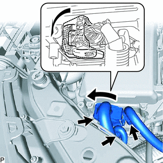
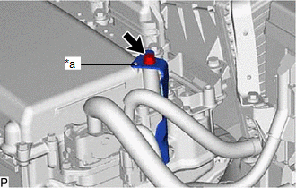
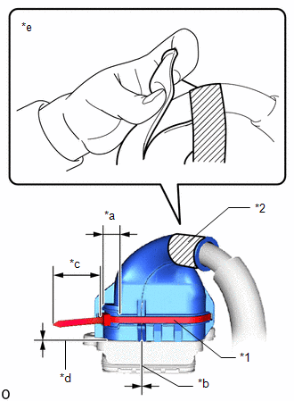
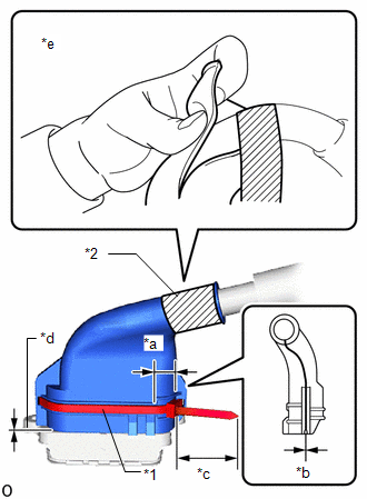
| (a) Connect the No. 1 inverter cooling hose assembly, and slide the retainer as shown in the illustration to secure. NOTICE:
HINT: When installing the quick connector, first turn it to the left, then return it to the right, and lock the retainer at the position where the retainer is facing up. |
|
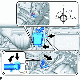
(b) Connect the inverter water hose to the inverter reserve tank sub-assembly, and secure with the hose clamp.
HINT:
Align the hose clamp at the position shown in the illustration.
(c) Install the inverter reserve tank sub-assembly with the 2 bolts.
Torque:
10 N·m {102 kgf·cm, 7 ft·lbf}
31. CONNECT WIRE HARNESS
(a) Secure the 4 wire harness clamps to the inverter reserve tank sub-assembly and inverter with converter assembly.
32. INSTALL SERVICE PLUG GRIP
Click here
33. ADD COOLANT (for Inverter Coolant)
Click here
34. INSPECT FOR COOLANT LEAK (for Inverter Coolant)
Click here
READ NEXT:
 Relay
Relay
On-vehicle InspectionON-VEHICLE INSPECTION PROCEDURE 1. INSPECT IGNITION CONTROL RELAY (IGCT) (a) Measure the resistance according to the value(s) in the table below. Standard Resistance: Test
Components
COMPONENTS ILLUSTRATION *1 DECK FLOOR BOX LH *2 NO. 3 DECK BOARD SUB-ASSEMBLY *3 REAR DECK FLOOR BOX *4 NEGATIVE AUXILIARY BATTERY TERMINAL N*m (kgf*cm, ft.*lbf): Specified
SEE MORE:
Freeze Frame Data
FREEZE FRAME DATA CHECK FREEZE FRAME DATA (a) Connect the Techstream to the DLC3. (b) Turn the power switch on (IG). (c) Turn the Techstream on. (d) Enter the following menus: Body Electrical / Navigation System / Trouble Codes. Body Electrical > Navigation System > Trouble Codes (e) Select a
Installation
INSTALLATION PROCEDURE 1. INSTALL ULTRASONIC SENSOR CUSHION SET HINT: Perform the following procedure only when replacement of a ultrasonic sensor cushion set is necessary. (a) Install the ultrasonic sensor cushion set as shown in the illustration. Install in this Direction - - 2. INST
