Lexus NX: Rear Power Window Switch
Components
COMPONENTS
ILLUSTRATION
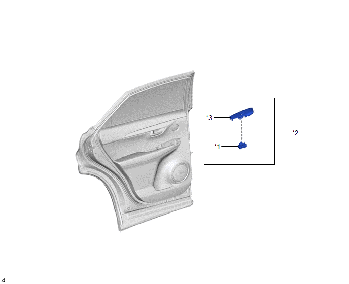
| *1 | REAR POWER WINDOW REGULATOR SWITCH ASSEMBLY | *2 | REAR POWER WINDOW REGULATOR SWITCH ASSEMBLY WITH REAR DOOR ARMREST BASE PANEL |
| *3 | REAR DOOR ARMREST BASE PANEL | - | - |
Removal
REMOVAL
CAUTION / NOTICE / HINT
HINT:
- Use the same procedure for the RH and LH sides.
- The procedure listed below is for the LH side.
PROCEDURE
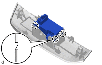
1. REMOVE REAR POWER WINDOW REGULATOR SWITCH ASSEMBLY WITH REAR DOOR ARMREST BASE PANEL
Click here .gif)
2. REMOVE REAR POWER WINDOW REGULATOR SWITCH ASSEMBLY
| (a) Detach the 3 claws and remove the rear power window regulator switch assembly. |
|
Inspection
INSPECTION
PROCEDURE
1. INSPECT REAR POWER WINDOW REGULATOR SWITCH ASSEMBLY
(a) Check the switch function.
| (1) Measure the resistance when the switch is operated according to the value(s) in the table below. Standard Resistance:
If the result is not as specified, replace the rear power window regulator switch assembly. |
|
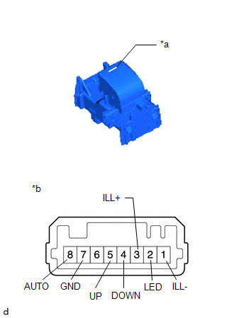
(b) Check that the LED illuminates.
(1) Apply auxiliary battery voltage to the rear power window regulator switch and check that the LED illuminates.
OK:
| Measurement Condition | Specified Condition |
|---|---|
| Auxiliary battery positive (+) → 3 (ILL+) Auxiliary battery negative (-) → 1 (ILL-) | LED illuminates |
If the result is not as specified, replace the rear power window regulator switch assembly.
Installation
INSTALLATION
CAUTION / NOTICE / HINT
HINT:
- Use the same procedure for the RH and LH sides.
- The procedure listed below is for the LH side.
PROCEDURE
1. INSTALL REAR POWER WINDOW REGULATOR SWITCH ASSEMBLY
(a) Attach the 3 claws to install the rear power window regulator switch assembly.
2. INSTALL REAR POWER WINDOW REGULATOR SWITCH ASSEMBLY WITH REAR DOOR ARMREST BASE PANEL
Click here .gif)
READ NEXT:
 Relay
Relay
On-vehicle InspectionON-VEHICLE INSPECTION PROCEDURE 1. INSPECT FRONT WIPER DEICER RELAY (a) Measure the resistance according to the value(s) in the table below. Standard Resistance: Tester Co
Parts Location
PARTS LOCATION ILLUSTRATION *1 AIR CONDITIONING CONTROL ASSEMBLY - REAR WINDOW DEFOGGER SWITCH *2 INSTRUMENT PANEL JUNCTION BLOCK ASSEMBLY - ECU-IG NO.1 FUSE - ECU-IG NO.3 FUSE *3 DLC3
SEE MORE:
Drive Motor "A" Phase V Current Sensor Circuit Range / Performance (P0BEA-290,...,P1C6E-502)
DTC SUMMARY MALFUNCTION DESCRIPTION These DTCs indicate the current sensor value is abnormal. The cause of this malfunction may be one of the following: Internal inverter malfunction
Inverter with converter assembly internal circuit malfunction
Inverter low-voltage circuit malfunction
The c
Dtc Check / Clear
DTC CHECK / CLEAR CHECK FOR DTC (a) Connect the Techstream to the DLC3. (b) Turn the power switch on (IG). (c) Turn the Techstream on. (d) Enter the following menus: Body Electrical / Main body / Trouble Codes. Body Electrical > Main Body > Trouble Codes (e) Enter the following menus: Body Ele
