Lexus NX: Parts Location
PARTS LOCATION
ILLUSTRATION
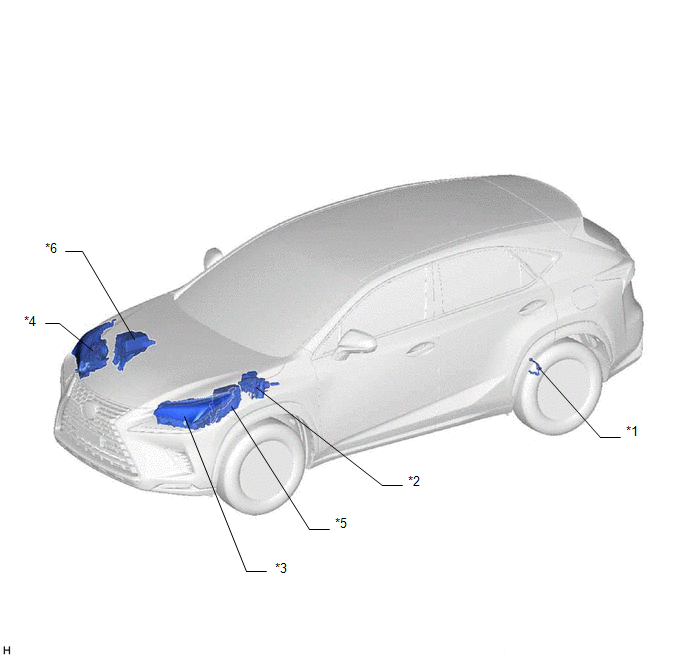
| *1 | REAR HEIGHT CONTROL SENSOR SUB-ASSEMBLY LH | *2 | BRAKE BOOSTER WITH MASTER CYLINDER ASSEMBLY (SKID CONTROL ECU) |
| *3 | HEADLIGHT ASSEMBLY LH - HEADLIGHT ECU SUB-ASSEMBLY LH - HEADLIGHT UNIT ASSEMBLY LH | *4 | HEADLIGHT ASSEMBLY RH - HEADLIGHT ECU SUB-ASSEMBLY RH - HEADLIGHT UNIT ASSEMBLY RH |
| *5 | ENGINE ROOM RELAY BLOCK - H-LP LH/DIMMER(HI) RELAY - H-LP MAIN LH/H-LP MAIN HI FUSE - H-LP MAIN RH/H-LP MAIN LO FUSE | *6 | NO. 2 ENGINE ROOM RELAY BLOCK - H-LP RH RELAY |
ILLUSTRATION
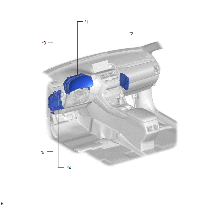
| *1 | COMBINATION METER ASSEMBLY | *2 | HYBRID VEHICLE CONTROL ECU |
| *3 | MAIN BODY ECU (MULTIPLEX NETWORK BODY ECU) | *4 | INSTRUMENT PANEL JUNCTION BLOCK ASSEMBLY - ECU-IG NO.3 FUSE |
| *5 | DLC3 | - | - |
READ NEXT:
 System Diagram
SYSTEM DIAGRAM
System Description
SYSTEM DESCRIPTION AUTOMATIC HEADLIGHT BEAM LEVEL CONTROL (a) General The automatic headlight beam level control system ensures forward visibility and prevents dazzling of drivers in oncoming and prec
How To Proceed With Troubleshooting
CAUTION / NOTICE / HINT HINT:
Use the following procedure to troubleshoot the automatic headlight beam level control system (for Triple Beam Headlight).
*: Use the Techstream
PROCEDURE 1.
SEE MORE:
Components
COMPONENTS ILLUSTRATION *1 REAR BUMPER COVER *2 REAR BUMPER NO. 1 PLATE *3 REAR FLOOR SIDE MEMBER COVER - - ILLUSTRATION *1 REAR BUMPER NO. 1 REINFORCEMENT *2 REAR BUMPER SIDE SEAL LH *3 REAR BUMPER SIDE SEAL RH *4 REAR BUMPER SIDE SUPPORT LH *5 REAR
Disassembly
DISASSEMBLY PROCEDURE 1. REMOVE HEADLIGHT WASHER ACTUATOR SUB-ASSEMBLY RH (w/ Headlight Cleaner System) Click here 2. REMOVE HEADLIGHT WASHER ACTUATOR SUB-ASSEMBLY LH (w/ Headlight Cleaner System) HINT: Use the same procedure described for the RH side. 3. REMOVE HEADLIGHT CLEANER WASHER NOZZLE COV
© 2016-2026 Copyright www.lexunx.com
