Lexus NX: Parts Location
PARTS LOCATION
ILLUSTRATION

| *A | w/ Rain Sensor | *B | w/ Headlight Cleaner System |
| *C | for Triple Beam Headlight | *D | for Single Beam Headlight |
| *1 | WINDSHIELD WIPER MOTOR ASSEMBLY | *2 | HEADLIGHT CLEANER CONTROL RELAY |
| *3 | HEADLIGHT CLEANER MOTOR AND PUMP ASSEMBLY | *4 | RAIN SENSOR |
| *5 | REAR WIPER MOTOR ASSEMBLY | *6 | HEADLIGHT CLEANER CONTROL RELAY |
| *7 | LEVEL WARNING SWITCH ASSEMBLY | *8 | WINDSHIELD WASHER MOTOR AND PUMP ASSEMBLY |
| *9 | WASHER NOZZLE SUB-ASSEMBLY | *10 | REAR WASHER NOZZLE |
| *11 | MAP LIGHT ASSEMBLY | *12 | HEADLIGHT CLEANER WASHER NOZZLE COVER |
| *13 | NO. 2 ENGINE ROOM RELAY BLOCK | *14 | H-LP CLN FUSE |
| *15 | WASHER-S FUSE | *16 | HEADLIGHT ECU SUB-ASSEMBLY RH |
| *17 | HEADLIGHT ECU SUB-ASSEMBLY LH | *18 | FUSE BLOCK |
| *19 | ECU-B NO.3 FUSE | - | - |
ILLUSTRATION
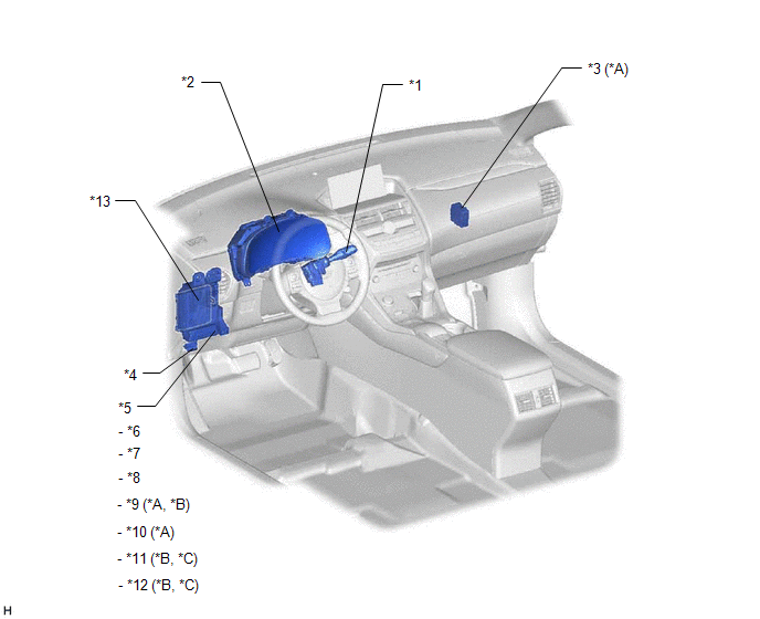
| *A | w/ Rain Sensor | *B | w/ Headlight Cleaner System |
| *C | for Single Beam Headlight | - | - |
| *1 | WINDSHIELD WIPER SWITCH ASSEMBLY | *2 | COMBINATION METER ASSEMBLY |
| *3 | WINDSHIELD WIPER RELAY ASSEMBLY | *4 | DLC3 |
| *5 | INSTRUMENT PANEL JUNCTION BLOCK ASSEMBLY | *6 | WIPER FUSE |
| *7 | WASHER FUSE | *8 | WIPER RR FUSE |
| *9 | ECU-IG NO.3 FUSE | *10 | ECU-IG NO.5 FUSE |
| *11 | ECU-IG NO.2 FUSE | *12 | ACC FUSE |
| *13 | MAIN BODY ECU (MULTIPLEX NETWORK BODY ECU) | - | - |
READ NEXT:
 System Diagram
SYSTEM DIAGRAM FRONT WIPER AND WASHER SYSTEM (w/ Rain Sensor) FRONT WIPER AND WASHER SYSTEM (w/o Rain Sensor) REAR WIPER AND WASHER SYSTEM HEADLIGHT CLEANER SYSTEM (w/ Headlight Cleaner System, fo
System Description
SYSTEM DESCRIPTION WASHER-LINKED FUNCTION (a) This system operates the front wipers at low speed immediately after spraying a jet of washer fluid when the front washer switch is turned on for 0.3 seco
How To Proceed With Troubleshooting
CAUTION / NOTICE / HINT HINT:
Use the following procedure to troubleshoot the wiper and washer system.
*: Use the Techstream.
PROCEDURE 1. VEHICLE BROUGHT TO WORKSHOP
NEXT
SEE MORE:
Components
COMPONENTS ILLUSTRATION *1 EXHAUST VALVE *2 EXHAUST VALVE GUIDE BUSH *3 INTAKE VALVE *4 INTAKE VALVE GUIDE BUSH *5 NO. 1 STRAIGHT SCREW PLUG *6 NO. 2 STRAIGHT SCREW PLUG *7 RING PIN *8 SPARK PLUG TUBE *9 VALVE SPRING SEAT *10 VALVE STEM OIL SEAL
Removal
REMOVAL PROCEDURE 1. PRECAUTION NOTICE: After turning the power switch is turned off, there may be a waiting time before disconnecting the auxiliary negative (-) battery terminal. Click here 2. CUSTOMIZE POWER TILT AND POWER TELESCOPIC STEERING COLUMN SYSTEM (a) Disable the auto tilt away function
