Lexus NX: Parts Location
PARTS LOCATION
ILLUSTRATION
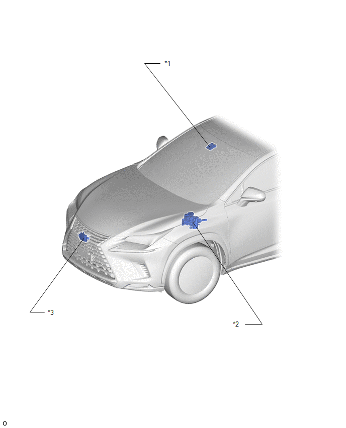
| *1 | FORWARD RECOGNITION CAMERA | *2 | BRAKE BOOSTER WITH MASTER CYLINDER ASSEMBLY - SKID CONTROL ECU |
| *3 | MILLIMETER WAVE RADAR SENSOR ASSEMBLY | - | - |
ILLUSTRATION
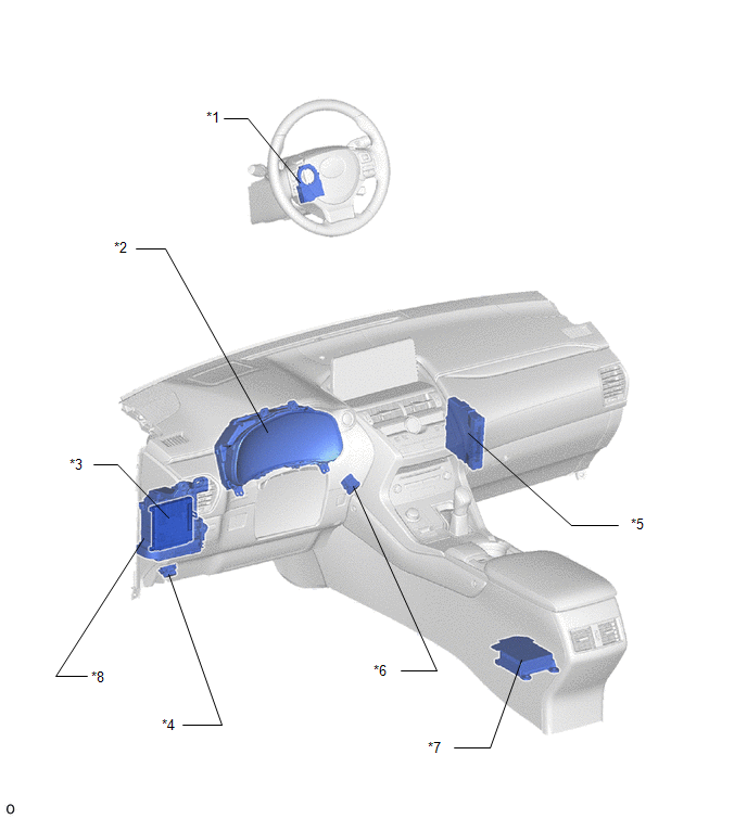
| *1 | STEERING SENSOR | *2 | COMBINATION METER ASSEMBLY |
| *3 | MAIN BODY ECU (MULTIPLEX NETWORK BODY ECU) | *4 | DLC3 |
| *5 | HYBRID VEHICLE CONTROL ECU | *6 | SKID CONTROL BUZZER |
| *7 | AIRBAG ECU ASSEMBLY | *8 | INSTRUMENT PANEL JUNCTION BLOCK ASSEMBLY - ECU-IG NO. 2 FUSE |
READ NEXT:
 System Diagram
SYSTEM DIAGRAM
How To Proceed With Troubleshooting
CAUTION / NOTICE / HINT HINT:
Use these procedures to troubleshoot the pre-collision system.
*: Use the Techstream.
PROCEDURE 1. VEHICLE BROUGHT TO WORKSHOP
NEXT 2
Customize Parameters
CUSTOMIZE PARAMETERS CUSTOMIZE PRE-COLLISION SYSTEM NOTICE:
When the customer requests a change in a function, first make sure that the function can be customized.
Make a note of the current sett
SEE MORE:
Diagnosis System
DIAGNOSIS SYSTEM DESCRIPTION (a) The DCM (telematics transceiver) control the vehicle safety connect system functions. Safety connect system data and Diagnostic Trouble Codes (DTCs) can be read through the vehicle Data Link Connector 3 (DLC3). In some cases, a malfunction may be occurring in the saf
Removal
REMOVAL CAUTION / NOTICE / HINT HINT:
Use the same procedure for the RH and LH sides.
The procedure listed below is for the LH side.
PROCEDURE 1. REMOVE REAR WHEEL Click here 2. DISCONNECT REAR SPEED SENSOR LH (a) w/o AVS: Click here (b) w/ AVS: Click here 3. REMOVE REAR SUSPENSION ARM
© 2016-2026 Copyright www.lexunx.com
