Lexus NX: Parts Location
PARTS LOCATION
ILLUSTRATION
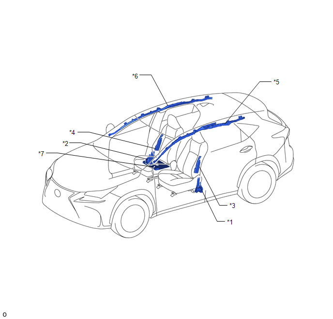
| *1 | FRONT SEAT OUTER BELT ASSEMBLY LH | *2 | FRONT SEAT OUTER BELT ASSEMBLY RH |
| *3 | FRONT SEAT AIRBAG ASSEMBLY LH | *4 | FRONT SEAT AIRBAG ASSEMBLY RH |
| *5 | CURTAIN SHIELD AIRBAG ASSEMBLY LH | *6 | CURTAIN SHIELD AIRBAG ASSEMBLY RH |
| *7 | FRONT SEAT CUSHION AIRBAG ASSEMBLY RH | - | - |
ILLUSTRATION
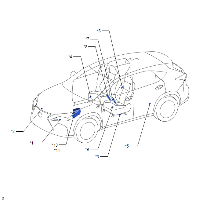
| *1 | FRONT AIRBAG SENSOR LH | *2 | FRONT AIRBAG SENSOR RH |
| *3 | DOOR SIDE AIRBAG SENSOR LH | *4 | DOOR SIDE AIRBAG SENSOR RH |
| *5 | SIDE AIRBAG SENSOR ASSEMBLY LH | *6 | SIDE AIRBAG SENSOR ASSEMBLY RH |
| *7 | FRONT SEAT INNER BELT ASSEMBLY LH | *8 | FRONT SEAT INNER BELT ASSEMBLY RH |
| *9 | SEAT POSITION AIRBAG SENSOR | *10 | ENGINE ROOM RELAY BLOCK AND JUNCTION BLOCK ASSEMBLY |
| *11 | METER NO. 1 FUSE | - | - |
ILLUSTRATION
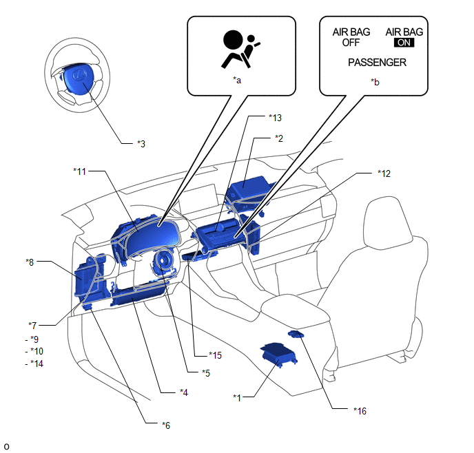
| *1 | AIRBAG ECU ASSEMBLY | *2 | INSTRUMENT PANEL PASSENGER AIRBAG ASSEMBLY |
| *3 | HORN BUTTON ASSEMBLY | *4 | LOWER NO. 1 INSTRUMENT PANEL AIRBAG ASSEMBLY |
| *5 | SPIRAL CABLE SUB-ASSEMBLY | *6 | DLC3 |
| *7 | INSTRUMENT PANEL JUNCTION BLOCK ASSEMBLY | *8 | MAIN BODY ECU (MULTIPLEX NETWORK BODY ECU) |
| *9 | A/BAG FUSE | *10 | METER NO. 2 FUSE |
| *11 | COMBINATION METER ASSEMBLY | *12 | HYBRID VEHICLE CONTROL ECU |
| *13 | AIR CONDITIONING CONTROL ASSEMBLY | *14 | ECU-IG NO. 2 FUSE |
| *15 | DCM (TELEMATICS TRANSCEIVER) | *16 | OCCUPANT DETECTION ECU |
| *a | SRS WARNING LIGHT | *b | PASSENGER AIRBAG ON/OFF INDICATOR |
READ NEXT:
 System Diagram
SYSTEM DIAGRAM Transmitting ECU (Transmitter) Receiving ECU (Receiver) Signal Communication Method Airbag ECU Assembly Hybrid Vehicle Control ECU Crash detection signal CAN C
System Description
SYSTEM DESCRIPTION GENERAL (a) Deceleration sensors used for the airbag system are installed on various parts of the vehicle and calculate the deceleration rate of each part during a collision. (b) De
How To Proceed With Troubleshooting
CAUTION / NOTICE / HINT HINT:
Use these procedures to troubleshoot the airbag system.
*: Use the Techstream.
PROCEDURE 1. VEHICLE BROUGHT TO WORKSHOP
NEXT 2. IN
SEE MORE:
Terminals Of Ecu
TERMINALS OF ECU MOBILE WIRELESS CHARGER CRADLE ASSEMBLY Terminal No. (Symbol) Wiring Color Terminal Description Condition Specified Condition
*1: When the power switch is turned from off to on (ACC), the mobile wireless charger cradle assembly checks the charging stop signal for 1 s
Problem Symptoms Table
PROBLEM SYMPTOMS TABLE NOTICE:
If the auxiliary battery voltage is low, the PTC heater, seat heater system (w/ Seat Heater System) and climate control seat system (w/ Climate Control Seat System) may not operate. When "High Power Consumption Partial Limit On AC/Heater Operation." is displayed on
