- SRS warning light on demand signal
- SRS warning light blink demand signal
- Diagnosis signal (DTC)
Lexus NX: System Diagram
Lexus NX Service Manual / Vehicle Interior / Supplemental Restraint Systems / Airbag System / System Diagram
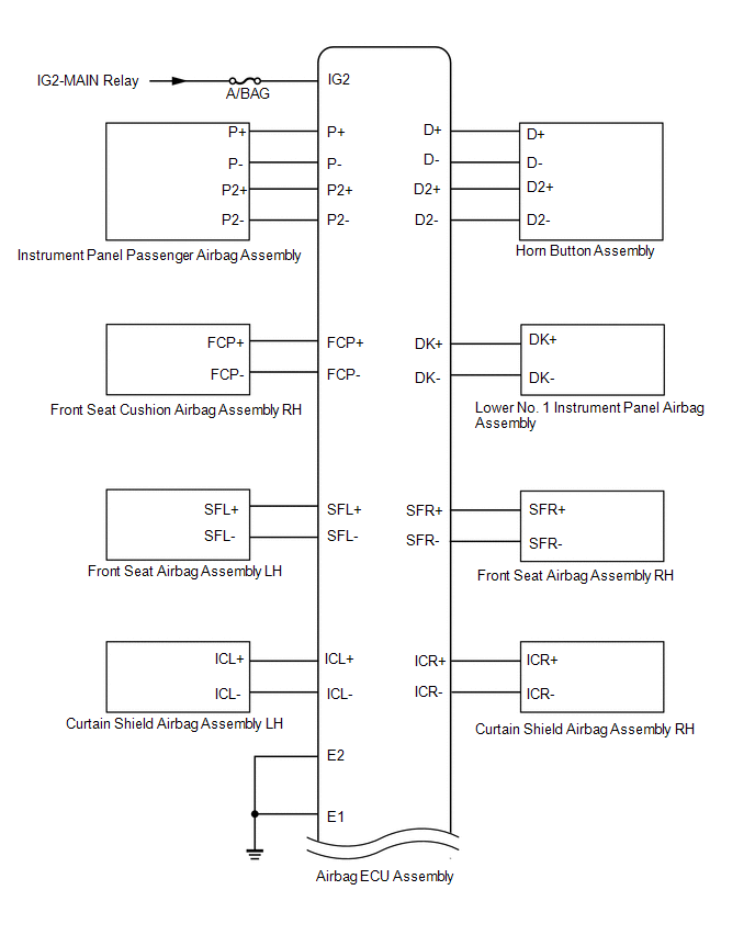
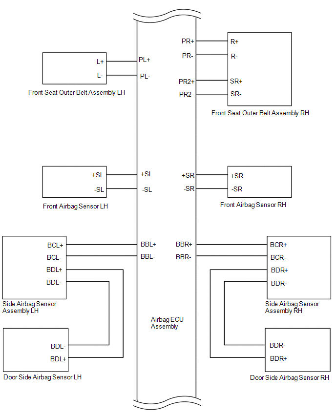
SYSTEM DIAGRAM
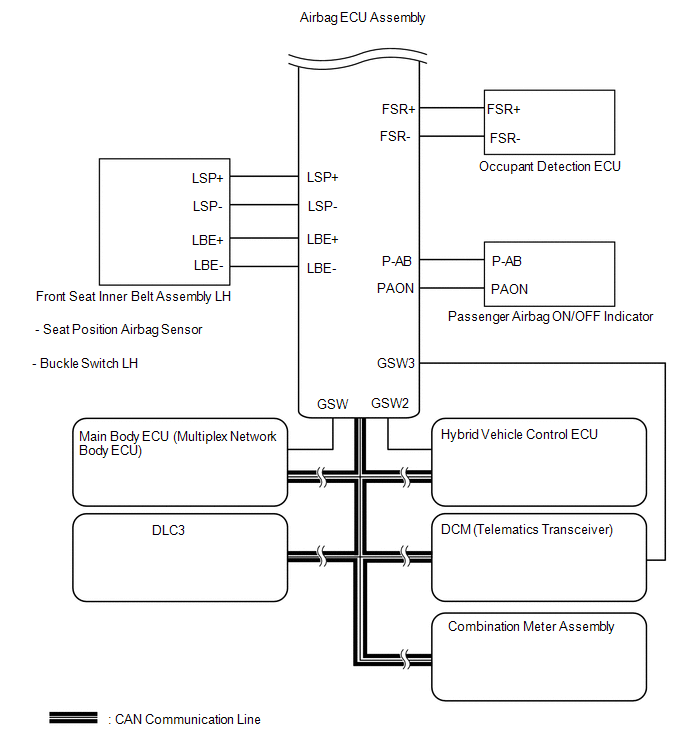
| Transmitting ECU (Transmitter) | Receiving ECU (Receiver) | Signal | Communication Method |
|---|---|---|---|
| Airbag ECU Assembly | Hybrid Vehicle Control ECU | Crash detection signal | CAN |
| Combination Meter Assembly | | ||
| Combination Meter Assembly |
| ||
| DCM (Telematics Transceiver) | |||
| Main Body ECU (Multiplex Network Body ECU) | Driver's seat belt buckle switch status signal | ||
| Telematics Transceiver | |||
| Hybrid Vehicle Control ECU | Airbag ECU Assembly |
|
READ NEXT:
 System Description
SYSTEM DESCRIPTION GENERAL (a) Deceleration sensors used for the airbag system are installed on various parts of the vehicle and calculate the deceleration rate of each part during a collision. (b) De
How To Proceed With Troubleshooting
CAUTION / NOTICE / HINT HINT:
Use these procedures to troubleshoot the airbag system.
*: Use the Techstream.
PROCEDURE 1. VEHICLE BROUGHT TO WORKSHOP
NEXT 2. IN
Problem Symptoms Table
PROBLEM SYMPTOMS TABLE HINT: Use the table below to help determine the cause of problem symptoms. If multiple suspected areas are listed, the potential causes of the symptoms are listed in order of pr
SEE MORE:
Inspection
INSPECTION PROCEDURE 1. INSPECT HEADLIGHT ASSEMBLY LH (a) Apply battery voltage to the connector and check the light illumination condition. OK: Battery Connection Specified Condition Positive (+) → 3 (LO) Negative (-) → 4 (E) Headlight illuminates Positive (+) → 2 (SOL) Neg
Generator Position Sensor Circuit Range / Performance (P0A4C-518,P0A4C-811)
DTC SUMMARY MALFUNCTION DESCRIPTION These DTCs indicate that a large current flowed in the inverter for the generator. The cause of this malfunction may be one of the following: Area Main Malfunction Description Step Inverter low-voltage circuit The connectors are not connected properly
© 2016-2026 Copyright www.lexunx.com
