Lexus NX: Parts Location
PARTS LOCATION
ILLUSTRATION
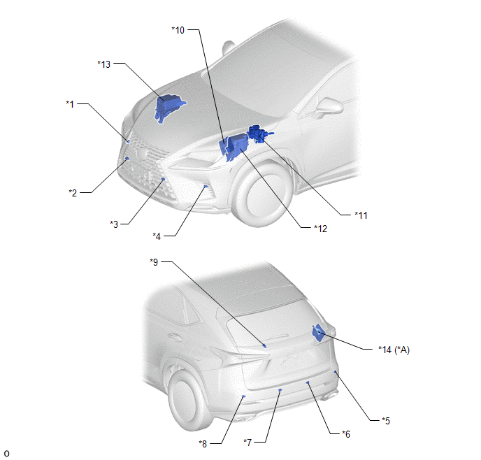
| *A | w/ Panoramic View Monitor System | - | - |
| *1 | FRONT CORNER ULTRASONIC SENSOR (FR SENSOR) | *2 | FRONT CENTER ULTRASONIC SENSOR (FRC SENSOR) |
| *3 | FRONT CENTER ULTRASONIC SENSOR (FLC SENSOR) | *4 | FRONT CORNER ULTRASONIC SENSOR (FL SENSOR) |
| *5 | REAR CORNER ULTRASONIC SENSOR (RR SENSOR) | *6 | REAR CENTER ULTRASONIC SENSOR (RRC SENSOR) |
| *7 | REAR CENTER ULTRASONIC SENSOR (RLC SENSOR) | *8 | REAR CORNER ULTRASONIC SENSOR (RL SENSOR) |
| *9 | NO. 2 CLEARANCE WARNING BUZZER | *10 | ECM |
| *11 | BRAKE BOOSTER WITH MASTER CYLINDER ASSEMBLY - SKID CONTROL ECU | *12 | ENGINE ROOM RELAY BLOCK - ECU-B NO.4 FUSE |
| *13 | NO. 2 ENGINE ROOM RELAY BLOCK - ECU-IG NO.6 FUSE | *14 | PARKING ASSIST ECU |
ILLUSTRATION
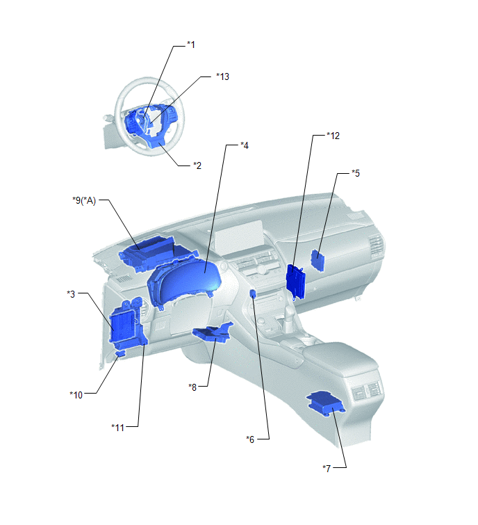
| *A | w/ Headup Display | - | - |
| *1 | SPIRAL CABLE SUB-ASSEMBLY | *2 | STEERING PAD SWITCH ASSEMBLY |
| *3 | MAIN BODY ECU (MULTIPLEX NETWORK BODY ECU) | *4 | COMBINATION METER ASSEMBLY |
| *5 | CLEARANCE WARNING ECU ASSEMBLY | *6 | NO. 1 CLEARANCE WARNING BUZZER |
| *7 | AIRBAG ECU ASSEMBLY | *8 | AIR CONDITIONING AMPLIFIER ASSEMBLY |
| *9 | METER MIRROR SUB-ASSEMBLY | *10 | DLC3 |
| *11 | INSTRUMENT PANEL JUNCTION BLOCK ASSEMBLY - ECU-IG NO.2 FUSE | *12 | HYBRID VEHICLE CONTROL ECU |
| *13 | STEERING SENSOR | - | - |
READ NEXT:
 System Diagram
SYSTEM DIAGRAM Communication Table Sender Receiver Signal Line Clearance Warning ECU Assembly Combination Meter Assembly
Sonar information signal
Control status signal
CAN
How To Proceed With Troubleshooting
CAUTION / NOTICE / HINT HINT:
Use the following procedure to troubleshoot the intelligent clearance sonar system.
*: Use the Techstream.
PROCEDURE 1. VEHICLE BROUGHT TO WORKSHOP
Operation Check
OPERATION CHECK ICS OFF INDICATOR LIGHT OPERATION CHECK (a) Turn the power switch on (IG). (b) Turn the intelligent clearance sonar system off and confirm that the ICS OFF indicator in the combination
SEE MORE:
Stereo Component Amplifier Malfunction (B15A3)
DESCRIPTION These DTCs are stored when a malfunction occurs in the stereo component amplifier assembly. DTC No. Detection Item DTC Detection Condition Trouble Area B15A3 Stereo Component Amplifier Malfunction When one of the conditions below is met:
Internal power supply malfunct
Removal
REMOVAL CAUTION / NOTICE / HINT HINT:
Use the same procedure for the RH and LH sides.
The procedure listed below is for the LH side.
PROCEDURE 1. REMOVE REAR WHEEL Click here 2. DISCONNECT REAR SPEED SENSOR LH (a) w/o AVS: Click here (b) w/ AVS: Click here 3. REMOVE REAR SUSPENSION ARM
