- Sonar information signal
- Control status signal
Lexus NX: System Diagram
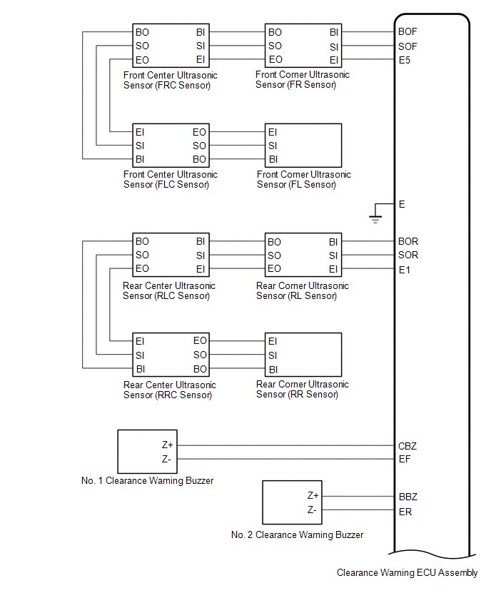
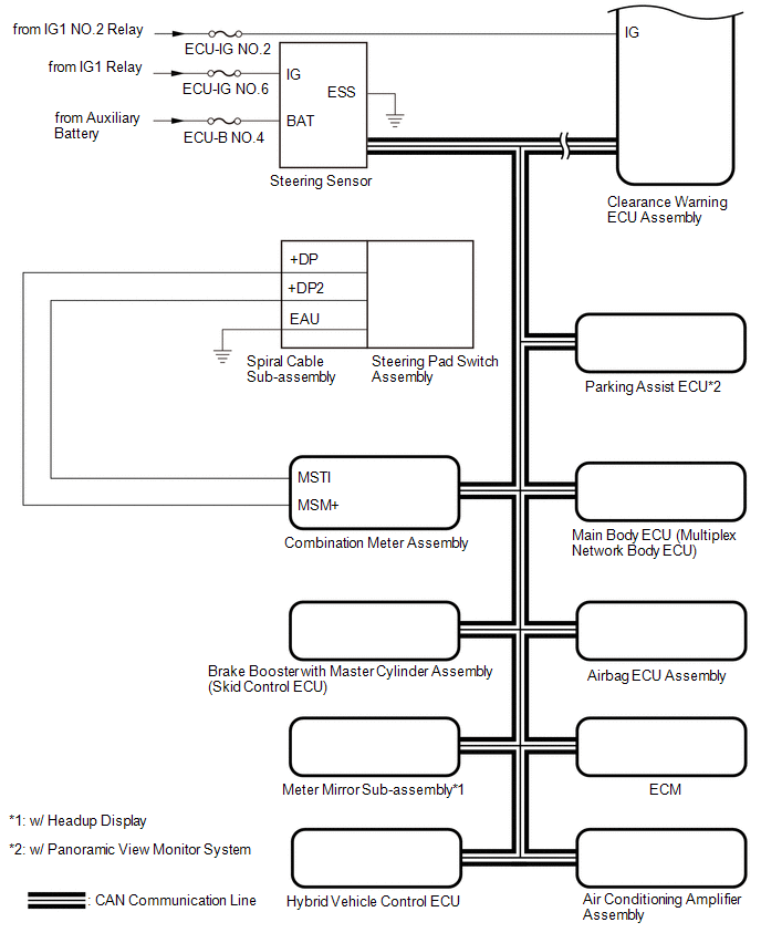
SYSTEM DIAGRAM
 Communication Table
 | Sender | Receiver | Signal | Line |
|---|---|---|---|
| Clearance Warning ECU Assembly | Combination Meter Assembly | | CAN Communication Line |
| ECM | Clearance Warning ECU Assembly | Engine speed signal | CAN Communication Line |
| Airbag ECU Assembly | Clearance Warning ECU Assembly | Yaw rate and acceleration sensor signal | CAN Communication Line |
| Combination Meter Assembly | Clearance Warning ECU Assembly | Vehicle speed signal | CAN Communication Line |
| Steering Sensor | Clearance Warning ECU Assembly | Steering angle signal | CAN Communication Line |
| Brake Booster with Master Cylinder Assembly (Skid Control ECU) | Clearance Warning ECU Assembly |
| CAN Communication Line |
| Air Conditioning Amplifier Assembly | Clearance Warning ECU Assembly | Ambient temperature signal | CAN Communication Line |
| Main Body ECU (Multiplex Network Body ECU) | Clearance Warning ECU Assembly | Vehicle information signal | CAN Communication Line |
| Clearance Warning ECU Assembly | Meter Mirror Sub-assembly*1 | Control status signal | CAN Communication Line |
| Clearance Warning ECU Assembly | Parking Assist ECU*2 | Control status signal | CAN Communication Line |
| Hybrid Vehicle Control ECU | Clearance Warning ECU Assembly | Shift position signal | CAN Communication Line |
- *1: w/ Headup Display
- *2: w/ Panoramic View Monitor System
READ NEXT:
 How To Proceed With Troubleshooting
CAUTION / NOTICE / HINT HINT:
Use the following procedure to troubleshoot the intelligent clearance sonar system.
*: Use the Techstream.
PROCEDURE 1. VEHICLE BROUGHT TO WORKSHOP
Operation Check
OPERATION CHECK ICS OFF INDICATOR LIGHT OPERATION CHECK (a) Turn the power switch on (IG). (b) Turn the intelligent clearance sonar system off and confirm that the ICS OFF indicator in the combination
Customize Parameters
CUSTOMIZE PARAMETERS CUSTOMIZE INTELLIGENT CLEARANCE SONAR SYSTEM (a) Customizing with the Techstream. NOTICE:
When the customer requests a change in a function, first make sure that the function c
SEE MORE:
Heated Oxygen Sensor
ComponentsCOMPONENTS ILLUSTRATION *1 FRONT EXHAUST PIPE SUB-ASSEMBLY *2 HEATED OXYGEN SENSOR *3 COMPRESSION SPRING *4 GASKET N*m (kgf*cm, ft.*lbf): Specified torque * For use with SST ● Non-reusable part - - RemovalREMOVAL PROCEDURE 1. REMOVE FRONT EXH
Dtc Check / Clear
DTC CHECK / CLEAR CHECK DTC (a) Connect the Techstream to the DLC3. (b) Turn the power switch on (IG). (c) Turn the Techstream on. (d) Enter the following menus: Body Electrical / Telematics / Trouble Codes. Body Electrical > Telematics > Trouble Codes (e) Check the details of the DTC(s). Clic
© 2016-2026 Copyright www.lexunx.com
