Lexus NX: Parts Location
PARTS LOCATION
ILLUSTRATION
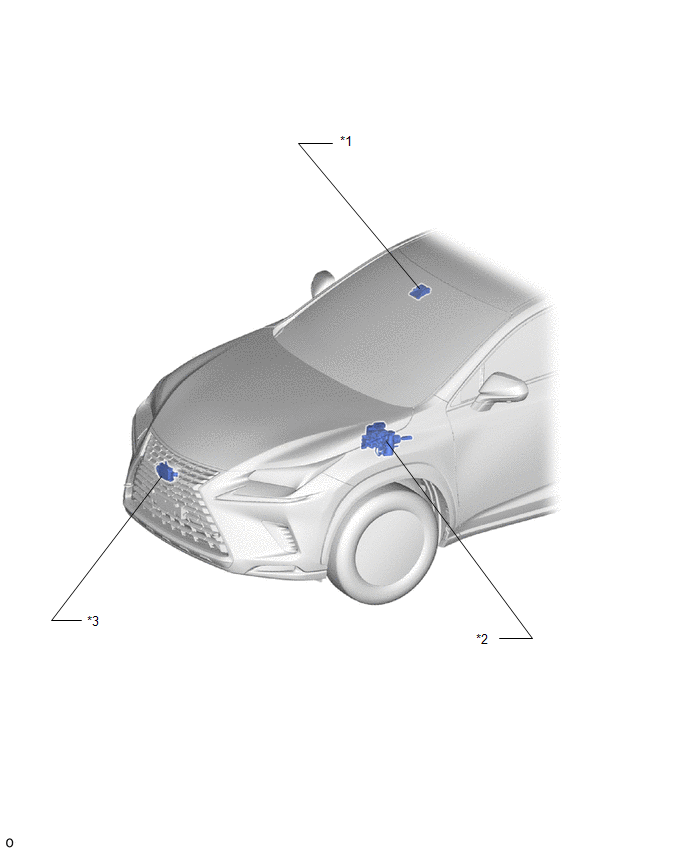
| *1 | FORWARD RECOGNITION CAMERA | *2 | BRAKE BOOSTER WITH MASTER CYLINDER ASSEMBLY - SKID CONTROL ECU |
| *3 | MILLIMETER WAVE RADAR SENSOR ASSEMBLY | - | - |
ILLUSTRATION
for Power Tilt and Power Telescopic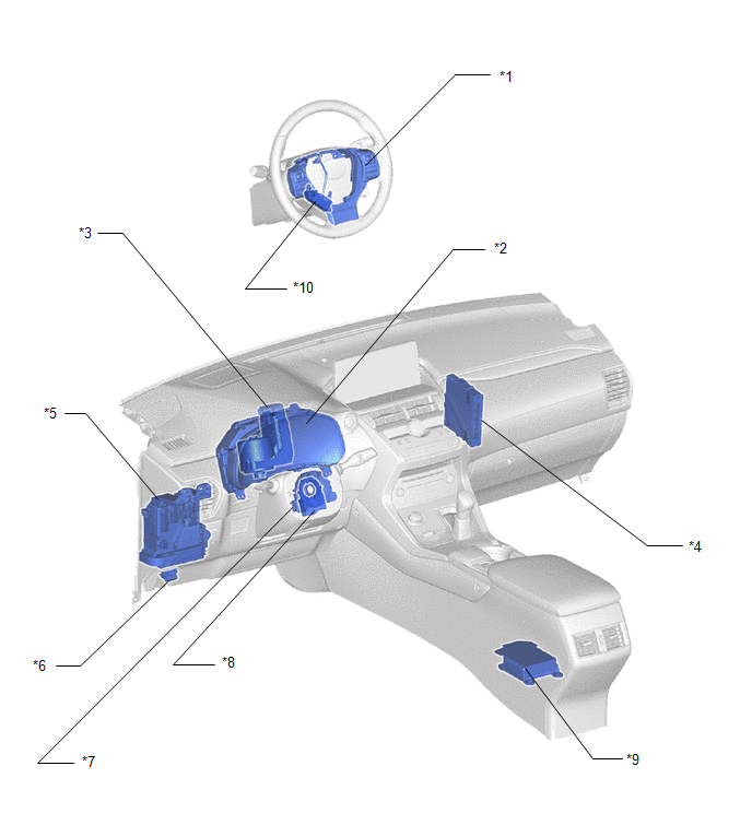
| *1 | STEERING PAD SWITCH ASSEMBLY - LTA/LDA MAIN SWITCH | *2 | COMBINATION METER ASSEMBLY - MULTI-INFORMATION DISPLAY - LTA/LDA INDICATOR LIGHT - LTA/LDA BUZZER (METER BUZZER) |
| *3 | POWER STEERING ECU ASSEMBLY | *4 | HYBRID VEHICLE CONTROL ECU |
| *5 | INSTRUMENT PANEL JUNCTION BLOCK ASSEMBLY - ECU-IG1 NO. 2 FUSE | *6 | DLC3 |
| *7 | SPIRAL CABLE SUB-ASSEMBLY | *8 | STEERING SENSOR |
| *9 | AIRBAG ECU ASSEMBLY | *10 | STEERING VIBRATION ECU |
ILLUSTRATION
for Manual Tilt and Manual Telescopic
| *1 | STEERING PAD SWITCH ASSEMBLY - LTA/LDA MAIN SWITCH | *2 | COMBINATION METER ASSEMBLY - MULTI-INFORMATION DISPLAY - LTA/LDA INDICATOR LIGHT - LTA/LDA BUZZER (METER BUZZER) |
| *3 | POWER STEERING ECU ASSEMBLY | *4 | HYBRID VEHICLE CONTROL ECU |
| *5 | INSTRUMENT PANEL JUNCTION BLOCK ASSEMBLY - ECU-IG1 NO. 2 FUSE | *6 | DLC3 |
| *7 | SPIRAL CABLE SUB-ASSEMBLY | *8 | STEERING SENSOR |
| *9 | AIRBAG ECU ASSEMBLY | *10 | STEERING VIBRATION ECU |
READ NEXT:
 System Diagram
SYSTEM DIAGRAM
How To Proceed With Troubleshooting
CAUTION / NOTICE / HINT HINT:
Use these procedures to troubleshoot the lane tracing assist system.
*: Use the Techstream.
PROCEDURE 1. VEHICLE BROUGHT TO WORKSHOP
NEXT
Customize Parameters
CUSTOMIZE PARAMETERS CUSTOMIZE LANE TRACING ASSIST SYSTEM (w/ Lane Centering Function) NOTICE:
When the customer requests a change in a function, first make sure that the function can be customized
SEE MORE:
Problem Symptoms Table
PROBLEM SYMPTOMS TABLE HINT:
Use the table below to help determine the cause of problem symptoms. If multiple suspected areas are listed, the potential causes of the symptom are listed in order of probability in the "Suspected Area" column of the table. Check each symptom by checking the suspecte
Removal
REMOVAL PROCEDURE 1. REMOVE DECK BOARD ASSEMBLY Click here 2. REMOVE NO. 3 DECK BOARD SUB-ASSEMBLY Click here 3. REMOVE REAR DECK FLOOR BOX Click here 4. REMOVE DECK FLOOR BOX LH Click here 5. PRECAUTION CAUTION: Be sure to read Precaution thoroughly before serving. Click here NOTICE: Afte
