Lexus NX: Power Back Door cannot be Operated Using Kick Sensor
DESCRIPTION
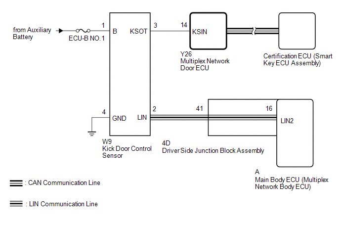
The kick door control sensor receives vehicle speed, IG and ACC signals from the main body ECU (multiplex network body ECU) via LIN communication and uses the information to stop sensor oscillation.
When the kick door control sensor detects a kick operation, it sends a operation signal to the multiplex network door ECU.
WIRING DIAGRAM
CAUTION / NOTICE / HINT
NOTICE:
-
Before troubleshooting, make sure that the "Kick Sensor Function" customize setting is set to "ON".
Click here
.gif)
-
Before troubleshooting, be sure to read Precautions for Hands Free Touchless Power Back Door.
Click here
-
If the multiplex network door ECU has been removed and installed or replaced, or if any of the connectors has been disconnected, initialize the power back door system.
Click here
-
After performing work, using the Techstream, read the Data List item "Kick Sensor Connection" and check that the kick door control sensor is connected.
Click here
PROCEDURE
| 1. | CHECK FOR DTC |
(a) Check for DTCs.
Click here
| Result | Proceed to |
|---|---|
| DTC is not output | A |
| DTC is output | B |
| B | .gif) | GO TO DIAGNOSTIC TROUBLE CODE CHART |
|
.gif)
| 2. | READ VALUE USING TECHSTREAM |
(a) Read the Data List according to the display on the Techstream.
Click here
| Tester Display | Measurement Item | Range | Normal Condition | Diagnostic Note |
|---|---|---|---|---|
| Kick Sensor Error | Status of the kick door control sensor error | Normal or Error | Normal: Kick door control sensor is normal Error: Kick door control sensor is abnormal | - |
| Tester Display |
|---|
| Kick Sensor Error |
OK:
On the Techstream, Normal is displayed.
| NG | | REPLACE KICK DOOR CONTROL SENSOR |
|
| 3. | READ VALUE USING TECHSTREAM |
(a) Read the Data List according to the display on the Techstream.
Click here
| Tester Display | Measurement Item | Range | Normal Condition | Diagnostic Note |
|---|---|---|---|---|
| Kick Sensor Detection | Status of the kick door control sensor detection | OFF or ON | OFF: Kick door control sensor not detecting a foot ON: Kick door control sensor detecting a foot | - |
| Tester Display |
|---|
| Kick Sensor Detection |
OK:
On Techstream screen, item changes between ON and OFF according to above chart.
| NG | | GO TO STEP 5 |
|
| 4. | CHECK HARNESS AND CONNECTOR (KICK DOOR CONTROL SENSOR - DRIVER SIDE JUNCTION BLOCK ASSEMBLY) |
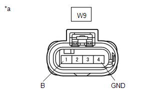
(a) Disconnect the W9 kick door control sensor connector.
(b) Disconnect the 4D driver side junction block assembly connector.
(c) Measure the resistance according to the value(s) in the table below.
Standard Resistance:
| Tester Connection | Condition | Specified Condition |
|---|---|---|
| W9-2 (LIN) - 4D-41 | Always | Below 1 Ω |
| OK | | REPLACE MULTIPLEX NETWORK DOOR ECU |
| NG | | REPAIR OR REPLACE HARNESS OR CONNECTOR |
| 5. | CHECK HARNESS AND CONNECTOR (KICK DOOR CONTROL SENSOR - BATTERY AND BODY GROUND) |
| (a) Disconnect the kick door control sensor connector. |
|
(b) Measure the voltage according to the value(s) in the table below.
Standard Resistance:
| Tester Connection | Condition | Specified Condition |
|---|---|---|
| W9-4 (GND) - Body ground | Always | Below 1 Ω |
(c) Measure the voltage according to the value(s) in the table below.
Standard Voltage:
| Tester Connection | Condition | Specified Condition |
|---|---|---|
| W9-1 (B) - Body ground | Always | 11 to 14 V |
| NG | | REPAIR OR REPLACE HARNESS OR CONNECTOR |
|
| 6. | CHECK HARNESS AND CONNECTOR (KICK DOOR CONTROL SENSOR - MULTIPLEX NETWORK DOOR ECU AND BODY GROUND) |
(a) Disconnect the W9 kick door control sensor connector.
(b) Disconnect the Y26 multiplex network door ECU connector.
(c) Measure the resistance according to the value(s) in the table below.
Standard Resistance:
| Tester Connection | Condition | Specified Condition |
|---|---|---|
| W9-3 (KSOT) - Y26-14 (KSIN) | Always | Below 1 Ω |
| W9-3 (KSOT) or Y26-14 (KSIN) - Body ground | Always | 10 kΩ or higher |
| NG | | REPAIR OR REPLACE HARNESS OR CONNECTOR |
|
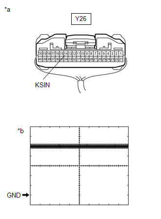
| 7. | CHECK MULTIPLEX NETWORK DOOR ECU |
(a) Remove the multiplex network door ECU with the connector(s) still connected.
Click here
| (b) Check the signal waveform according to the condition(s) in the table below. Measurement Condition
OK: The waveform displayed is as shown in the illustration. |
|
| OK | | REPLACE KICK DOOR CONTROL SENSOR |
| NG | | REPLACE MULTIPLEX NETWORK DOOR ECU |
READ NEXT:
 Lock Function does not Operate (Close &)
DESCRIPTION The door control switch signal is sent to the multiplex network door ECU. If the power back door system does not operate when the door control switch is operated, the door control switch c
Components
COMPONENTS ILLUSTRATION *1 BACK DOOR CENTER GARNISH *2 BACK DOOR LOCK COVER *3 BACK DOOR SIDE GARNISH LH *4 BACK DOOR SIDE GARNISH RH *5 BACK DOOR TRIM BASE *6 BACK DOOR
SEE MORE:
Dtc Check / Clear
DTC CHECK / CLEAR DTC CHECK (a) Turn the power switch off. (b) Connect the Techstream to the DLC3. (c) Turn the power switch on (IG). (d) Turn the Techstream on. (e) Enter the following menus: Body Electrical / Occupant Detection / Trouble Codes. (f) Check for DTCs by following the prompts on the Te
Skid Control ECU Communication Stop Mode
DESCRIPTION Detection Item Symptom Trouble Area Skid Control ECU Communication Stop Mode Any of the following conditions are met:
Communication stop for "Skid Control (ABS/VSC/TRAC)" is indicated on "Communication Bus Check".
Click here
Communication system DTCs (DTCs that star
