Lexus NX: Lock Function does not Operate (Close &)
DESCRIPTION
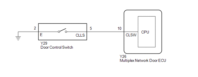
The door control switch signal is sent to the multiplex network door ECU. If the power back door system does not operate when the door control switch is operated, the door control switch circuit may be malfunctioning.
WIRING DIAGRAM
CAUTION / NOTICE / HINT
NOTICE:
If the replacement, removal and installation of the multiplex network door ECU or disconnection of the connectors of the multiplex network door ECU has been performed, initialize the power back door system.
Click here .gif)
PROCEDURE
| 1. | READ VALUE USING TECHSTREAM |
(a) Read the Data List according to the display on the Techstream.
Click here
| Tester Display | Measurement Item | Range | Normal Condition | Diagnostic Note |
|---|---|---|---|---|
| Close and Lock SW | Door control switch signal | ON or OFF | ON: Door control switch pushed OFF: Door control switch not pushed | - |
| Tester Display |
|---|
| Close and Lock SW |
OK:
The door control switch functions as specified in the normal condition column.
| OK | .gif) | REPLACE MULTIPLEX NETWORK DOOR ECU |
|
.gif)
| 2. | INSPECT DOOR CONTROL SWITCH |
(a) Remove the door control switch.
Click here
(b) Inspect the door control switch.
Click here
| NG | | REPLACE DOOR CONTROL SWITCH |
|
| 3. | CHECK HARNESS AND CONNECTOR (DOOR CONTROL SWITCH - MULTIPLEX NETWORK DOOR ECU AND BODY GROUND) |
(a) Disconnect the Y29 door control switch connector.
(b) Disconnect the Y26 multiplex network door ECU connector.
(c) Measure the resistance according to the value(s) in the table below.
Standard Resistance:
| Tester Connection | Condition | Specified Condition |
|---|---|---|
| Y29-5 (CLLS) - Y26-10 (CLSW) | Always | Below 1 Ω |
| Y29-2 (E) - Body ground | Always | Below 1 Ω |
| Y29-5 (CLLS) or Y26-10 (CLSW) - Body ground | Always | 10 kΩ or higher |
| OK | | REPLACE MULTIPLEX NETWORK DOOR ECU |
| NG | | REPAIR OR REPLACE HARNESS OR CONNECTOR |
READ NEXT:
 Components
COMPONENTS ILLUSTRATION *1 BACK DOOR CENTER GARNISH *2 BACK DOOR LOCK COVER *3 BACK DOOR SIDE GARNISH LH *4 BACK DOOR SIDE GARNISH RH *5 BACK DOOR TRIM BASE *6 BACK DOOR
Removal
REMOVAL CAUTION / NOTICE / HINT HINT:
Use the same procedure for the RH and LH sides.
The procedure listed below is for the LH side.
PROCEDURE 1. REMOVE BACK DOOR CENTER GARNISH Click here
SEE MORE:
Inspection
INSPECTION PROCEDURE 1. INSPECT REAR HEADER SPEAKER ASSEMBLY (a) Measure the resistance according to the value(s) in the table below. Standard Resistance: Tester Connection Condition Specified Condition 1 - 2 Always 7.0 to 10.6 Ω If the result is not as specified, replace the
Installation
INSTALLATION PROCEDURE 1. INSTALL TIMING CHAIN COVER OIL SEAL (a) w/o Side Lip: (1) Apply MP grease to the lip of a new timing chain cover oil seal. NOTICE:
Do not allow foreign matter to contact the lip of the timing chain cover oil seal.
Do not allow MP grease to contact the dust seal.
