Lexus NX: Removal
REMOVAL
CAUTION / NOTICE / HINT
HINT:
- Use the same procedure for the RH and LH sides.
- The procedure listed below is for the LH side.
PROCEDURE
1. REMOVE BACK DOOR CENTER GARNISH
Click here .gif)
2. REMOVE BACK DOOR SIDE GARNISH LH
Click here
3. REMOVE BACK DOOR SIDE GARNISH RH
Click here
4. REMOVE BACK DOOR TRIM BASE
Click here
5. REMOVE PULL HANDLE
Click here
6. REMOVE BACK DOOR LOCK COVER
Click here
7. REMOVE BACK DOOR TRIM BOARD ASSEMBLY
Click here
8. REMOVE POWER BACK DOOR UNIT ASSEMBLY SET LH
| (a) Disconnect the connector. |
|
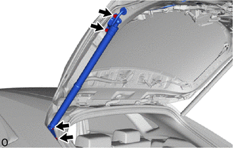
(b) Detach the grommet.
(c) Remove the 4 bolts and power back door unit assembly set LH.
9. REMOVE BACK DOOR LOWER DAMPER STAY BRACKET LH
(a) Perform this procedure when replacing only the back door lower damper stay bracket LH.
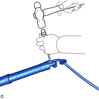
(1) Using a 3 mm pin punch and hammer, tap out the pin from the joint.
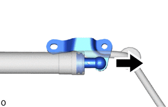
| (2) Remove the joint and protector cover. |
|
READ NEXT:
 Installation
INSTALLATION CAUTION / NOTICE / HINT HINT:
Use the same procedure for the RH and LH sides.
The procedure listed below is for the LH side.
PROCEDURE 1. INSTALL BACK DOOR LOWER DAMPER STAY BRACK
Power Back Door Main Switch
InspectionINSPECTION PROCEDURE 1. INSPECT POWER BACK DOOR MAIN SWITCH (a) Check the resistance. (1) Measure the resistance according to the value(s) in the table below. Standard Resistance: Te
SEE MORE:
System Description
SYSTEM DESCRIPTION GENERAL (a) In the occupant classification system, the occupant detection ECU calculates the weight of the occupant based on signals from the occupant classification sensors. This system recognizes the occupant as a child if it detects a weight of less than 17 kg (37.4 lb) on the
Disassembly
DISASSEMBLY PROCEDURE 1. REMOVE ENGINE COVER JOINT (a) Remove the 3 engine cover joints. 2. REMOVE SPARK PLUG Click here 3. REMOVE KNOCK CONTROL SENSOR Click here 4. REMOVE ENGINE COOLANT TEMPERATURE SENSOR Click here 5. REMOVE ENGINE OIL PRESSURE SWITCH ASSEMBLY Click here 6.
