Lexus NX: Power Mirror Surface Position is not Memorized
DESCRIPTION
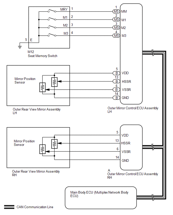
When the seat memory switch is operated, the switch input signal is sent via CAN communication from the outer mirror control ECU assembly LH to the main body ECU (multiplex network body ECU). The main body ECU (multiplex network body ECU) then sends the memorization request or recall request signals to the outer mirror control ECU assembly LH and outer mirror control ECU assembly RH via CAN communication. The outer mirror control ECU assembly LH and outer mirror control ECU assembly RH memorize the mirror position when a memorization request signal is received, and move the mirror to the memorized position when a recall request signal is received.
WIRING DIAGRAM
CAUTION / NOTICE / HINT
NOTICE:
-
First perform the communication function inspections in How to Proceed with Troubleshooting to confirm that there are no CAN communication malfunctions before troubleshooting this problem.
Click here
.gif)
-
If the main body ECU (multiplex network body ECU) is replaced, refer to Registration.
Click here
PROCEDURE
| 1. | CHECK OUTER REAR VIEW MIRROR ASSEMBLY FUNCTION |
(a) Check that the mirror operates.
Click here
OK:
Mirror operates normally.
| Result | Proceed to |
|---|---|
| OK | A |
| NG (Driver side outer rear view mirror assembly does not operate) | B |
| NG (Front passenger side outer rear view mirror assembly does not operate) | C |
| B | .gif) | GO TO OTHER FLOWCHART (Driver Side Power Mirror cannot be Adjusted with Power Mirror Switch) |
| C | | GO TO OTHER FLOWCHART (Front Passenger Side Power Mirror cannot be Adjusted with Power Mirror Switch) |
|
.gif)
| 2. | CHECK SEAT MEMORY SWITCH (SEAT POSITION MEMORY FUNCTION) |
(a) Perform a seat memory operation properly.
Click here
(b) When any seat memory switch (M1, M2 or M3 switch) is pressed, check that the driver side seat moves to the memorized position.
OK:
Driver side seat moves to memorized position.
| NG | | GO TO FRONT POWER SEAT CONTROL SYSTEM |
|
| 3. | READ VALUE USING TECHSTREAM |
(a) Using the Techstream, read the Data List.
Click here
(1) for LH side
Body Electrical > Mirror L > Data List| Tester Display | Measurement Item | Range | Normal Condition | Diagnostic Note |
|---|---|---|---|---|
| Mirror Memory No.1 | Mirror position memorized in memory switch M1 | OFF or ON | OFF: Not memorized ON: Memorized | - |
| Mirror Memory No.2 | Mirror position memorized in memory switch M2 | OFF or ON | OFF: Not memorized ON: Memorized | - |
| Mirror Memory No.3 | Mirror position memorized in memory switch M3 | OFF or ON | OFF: Not memorized ON: Memorized | - |
| Tester Display |
|---|
| Mirror Memory No.1 |
| Mirror Memory No.2 |
| Mirror Memory No.3 |
(2) for RH side
Body Electrical > Mirror R > Data List| Tester Display | Measurement Item | Range | Normal Condition | Diagnostic Note |
|---|---|---|---|---|
| Mirror Memory No.1 | Mirror position memorized in memory switch M1 | OFF or ON | OFF: Not memorized ON: Memorized | - |
| Mirror Memory No.2 | Mirror position memorized in memory switch M2 | OFF or ON | OFF: Not memorized ON: Memorized | - |
| Mirror Memory No.3 | Mirror position memorized in memory switch M3 | OFF or ON | OFF: Not memorized ON: Memorized | - |
| Tester Display |
|---|
| Mirror Memory No.1 |
| Mirror Memory No.2 |
| Mirror Memory No.3 |
OK:
The display is as specified in the normal condition column.
| Result | Proceed to |
|---|---|
| LH side mirror position cannot be memorized | A |
| LH side mirror position memory exists but cannot be recalled | B |
| RH side mirror position cannot be memorized | C |
| RH side mirror position memory exists but cannot be recalled | D |
| Both LH side mirror position and RH side mirror position cannot be memorized | E |
| B | | REPLACE OUTER MIRROR CONTROL ECU ASSEMBLY LH |
| C | | GO TO STEP 5 |
| D | | REPLACE OUTER MIRROR CONTROL ECU ASSEMBLY RH |
| E | | REPLACE MAIN BODY ECU (MULTIPLEX NETWORK BODY ECU) |
|
| 4. | CHECK OUTER REAR VIEW MIRROR ASSEMBLY LH |
(a) Temporarily replace the outer rear view mirror assembly LH with a new or normally functioning one.
Click here
(b) Check that the memory and reactivation function operates.
Click here
OK:
Memory and reactivation function operates normally.
| OK | | END (OUTER REAR VIEW MIRROR ASSEMBLY LH IS DEFECTIVE) |
| NG | | REPLACE OUTER MIRROR CONTROL ECU ASSEMBLY LH |
| 5. | CHECK OUTER REAR VIEW MIRROR ASSEMBLY RH |
(a) Temporarily replace the outer rear view mirror assembly RH with a new or normally functioning one.
Click here
(b) Check that the memory and reactivation function operates.
Click here
OK:
Memory and reactivation function operates normally.
| OK | | END (OUTER REAR VIEW MIRROR ASSEMBLY RH IS DEFECTIVE) |
| NG | | REPLACE OUTER MIRROR CONTROL ECU ASSEMBLY RH |
READ NEXT:
 Reverse Shift-linked Function of Power Mirrors does not Operate
DESCRIPTION Hybrid vehicle control ECU sends the reverse signal to the main body ECU (multiplex network body ECU) via CAN communication. When receiving the reverse signal, the main body ECU (multiplex
Parts Location
PARTS LOCATION ILLUSTRATION *1 OUTER REAR VIEW MIRROR ASSEMBLY LH *2 OUTER REAR VIEW MIRROR ASSEMBLY RH *3 OUTER MIRROR LH *4 OUTER MIRROR RH *5 NO. 2 ENGINE ROOM RELAY BLOCK
SEE MORE:
Operation Check
OPERATION CHECK NOTICE: When using both Fleet Apps and Infotainment Apps together at the same time, it is not possible to remove only one type of app. By using "Delete all personal data from the head unit", both types of apps will be removed. LEXUS APP SUITE RESET PROCEDURE (When using Fleet Apps) (
Engine Coolant Temperature Circuit Range / Performance (P0116)
DESCRIPTION Refer to DTC P0115. Click here DTC No. Detection Item DTC Detection Condition Trouble Area MIL Memory P0116 Engine Coolant Temperature Circuit Range / Performance Either of the following conditions is met (2 trip detection logic):
When engine is started cold and
