Lexus NX: Parts Location
PARTS LOCATION
ILLUSTRATION
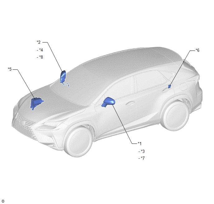
| *1 | OUTER REAR VIEW MIRROR ASSEMBLY LH | *2 | OUTER REAR VIEW MIRROR ASSEMBLY RH |
| *3 | OUTER MIRROR LH | *4 | OUTER MIRROR RH |
| *5 | NO. 2 ENGINE ROOM RELAY BLOCK - DEF RELAY - ECU-B NO.2 FUSE - DEF FUSE - MIR HTR FUSE - MIRROR FUSE | *6 | FUSE BLOCK ASSEMBLY - ECU-B NO.3 FUSE |
| *7 | OUTER MIRROR RETRACTOR LH | *8 | OUTER MIRROR RETRACTOR RH |
ILLUSTRATION
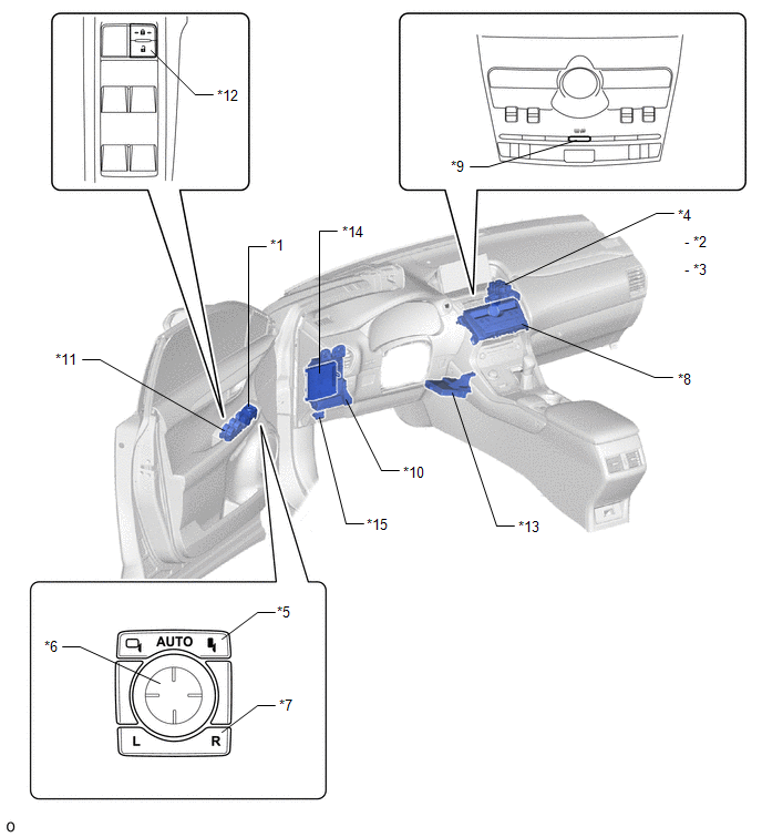
| *1 | OUTER MIRROR SWITCH ASSEMBLY | *2 | E-MIR1 RELAY |
| *3 | E-MIR2 RELAY | *4 | NO. 3 RELAY BLOCK ASSEMBLY |
| *5 | MIRROR RETRACT SWITCH | *6 | MIRROR SURFACE ADJUST SWITCH |
| *7 | MIRROR SELECT SWITCH | *8 | AIR CONDITIONING CONTROL ASSEMBLY |
| *9 | REAR WINDOW DEFOGGER SWITCH | *10 | INSTRUMENT PANEL JUNCTION BLOCK ASSEMBLY - ECU-IG NO.1 FUSE - ECU-IG NO.2 FUSE - ECU-IG NO.3 FUSE - ACC FUSE |
| *11 | MULTIPLEX NETWORK MASTER SWITCH ASSEMBLY | *12 | DOOR CONTROL SWITCH |
| *13 | AIR CONDITIONING AMPLIFIER ASSEMBLY | *14 | MAIN BODY ECU (MULTIPLEX NETWORK BODY ECU) |
| *15 | DLC3 | - | - |
READ NEXT:
 System Diagram
SYSTEM DIAGRAM Power Mirror Control System Mirror Heater System
System Description
SYSTEM DESCRIPTION FUNCTION OF MAIN COMPONENT Component Function Outer rear view mirror assembly Vertical mirror motor Moves the mirror surface vertically in accordance with the vertical
How To Proceed With Troubleshooting
CAUTION / NOTICE / HINT HINT:
Use the following procedure to troubleshoot the power mirror control system.
*: Use the Techstream.
PROCEDURE 1. VEHICLE BROUGHT TO WORKSHOP
NEXT
SEE MORE:
Light Sensor Circuit Malfunction (B1244)
DESCRIPTION The automatic light control sensor detects ambient light, converts it into an electrical signal and outputs it to the main body ECU (multiplex network body ECU). The main body ECU (multiplex network body ECU) turns the headlights and taillights on or off according to the signal. The main
Back Door Support
ComponentsCOMPONENTS ILLUSTRATION *1 BACK DOOR LOWER DAMPER STAY BRACKET LH *2 BACK DOOR STAY ASSEMBLY LH *3 BACK DOOR UPPER DAMPER STAY BRACKET LH - - N*m (kgf*cm, ft.*lbf): Specified torque ★ Precoated part RemovalREMOVAL CAUTION / NOTICE / HINT HINT:
Use t
