Lexus NX: Power Retractable Mirrors do not Operate with Power Retract Mirror Switch
DESCRIPTION
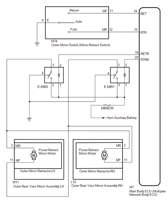
When the outer mirror switch assembly (mirror retract switch) is operated, a retract/return signal is received by the main body ECU (multiplex network body ECU). The main body ECU (multiplex network body ECU) retracts and returns the outer rear view mirror assembly based on the received signal.
WIRING DIAGRAM
CAUTION / NOTICE / HINT
NOTICE:
- Inspect the fuses for circuits related to this system before performing the following inspection procedure.
-
If the main body ECU (multiplex network body ECU) is replaced, refer to Registration.
Click here
.gif)
PROCEDURE
| 1. | READ VALUE USING TECHSTREAM (OUTER MIRROR FOLD SW) |
(a) Connect the Techstream to the DLC3.
(b) Turn the power switch on (IG).
(c) Turn the Techstream on.
(d) Enter the following menus: Body Electrical / Main Body / Data List.
(e) Read the Data List according to the display on the Techstream.
Body Electrical > Main Body > Data List| Tester Display | Measurement Item | Range | Normal Condition | Diagnostic Note |
|---|---|---|---|---|
| Outer Mirror Fold SW | Mirror retract switch signal | ON/OFF | ON: Mirror retract switch in retract position OFF: Mirror retract switch not in retract position | - |
| Outer Mirror Return SW | Mirror retract switch signal | ON/OFF | ON: Mirror retract switch in return position OFF: Mirror retract switch not in return position | - |
| Tester Display |
|---|
| Outer Mirror Fold SW |
| Outer Mirror Return SW |
OK:
On the Techstream screen, ON or OFF is displayed for each item according to the table above.
| NG | .gif) | GO TO STEP 8 |
|
.gif)
| 2. | CHECK MALFUNCTIONING PARTS |
(a) Check the malfunctioning parts.
Click here
| Result | Proceed to |
|---|---|
| Both mirrors are malfunctioning | A |
| RH side mirror is malfunctioning | B |
| LH side mirror is malfunctioning | C |
| B | | GO TO STEP 10 |
| C | | GO TO STEP 12 |
|
| 3. | INSPECT AUTO RETRACT RELAY (E-MIR1, E-MIR2) |
(a) Remove the E-MIR1 and E-MIR2 relay from the No. 3 relay block assembly.
(b) Inspect the E-MIR1 and E-MIR2 relay.
Click here
| NG | | REPLACE AUTO RETRACT RELAY |
|
| 4. | CHECK HARNESS AND CONNECTOR (AUTO RETRACT RELAY - BATTERY) |
(a) Remove the E-MIR1 and E-MIR2 relay.
| (b) Measure the voltage according to the value(s) in the table below. Standard Voltage:
|
|
| NG | | REPAIR OR REPLACE HARNESS OR CONNECTOR |
|
| 5. | CHECK HARNESS AND CONNECTOR (AUTO RETRACT RELAY - BODY GROUND) |
(a) Remove the E-MIR1 and E-MIR2 relay.
| (b) Measure the resistance according to the value(s) in the table below. Standard Resistance:
|
|
| NG | | REPAIR OR REPLACE HARNESS OR CONNECTOR |
|
| 6. | CHECK HARNESS AND CONNECTOR (AUTO RETRACT RELAY - MAIN BODY ECU [MULTIPLEX NETWORK BODY ECU]) |
(a) Remove the E-MIR1 and E-MIR2 relay.
(b) Measure the resistance according to the value(s) in the table below.
Standard Resistance:
| Tester Connection | Condition | Specified Condition |
|---|---|---|
| E-MIR1 relay holder terminal-2 - I47-20 (RTRR) | Always | Below 1 Ω |
| E-MIR1 relay holder terminal-2 - Body ground | Always | 10 kΩ or higher |
| E-MIR2 relay holder terminal-2 - I47-19 (RETR) | Always | Below 1 Ω |
| E-MIR2 relay holder terminal-2 - Body ground | Always | 10 kΩ or higher |
| NG | | REPAIR OR REPLACE HARNESS OR CONNECTOR |
|
| 7. | CHECK HARNESS AND CONNECTOR (AUTO RETRACT RELAY - OUTER REAR VIEW MIRROR ASSEMBLY RH OR LH) |
(a) Remove the E-MIR1 and E-MIR2 relay.
(b) Disconnect the L12 outer rear view mirror assembly RH or M11 outer rear view mirror assembly LH connector.
(c) Measure the resistance according to the value(s) in the table below.
Standard Resistance:
| Tester Connection | Condition | Specified Condition |
|---|---|---|
| E-MIR1 relay holder terminal-3 - L12-11 (MF) or M11-11 (MF) | Always | Below 1 Ω |
| E-MIR2 relay holder terminal-3 - L12-3 (MR) or M11-3 (MR) | Always | Below 1 Ω |
| OK | | REPLACE MAIN BODY ECU (MULTIPLEX NETWORK BODY ECU) |
| NG | | REPAIR OR REPLACE HARNESS OR CONNECTOR |
| 8. | INSPECT OUTER MIRROR SWITCH ASSEMBLY (MIRROR RETRACT SWITCH) |
(a) Remove the outer mirror switch assembly.
Click here
(b) Inspect the outer mirror switch assembly.
Click here
| NG | | REPLACE OUTER MIRROR SWITCH ASSEMBLY |
|
| 9. | CHECK HARNESS AND CONNECTOR (OUTER MIRROR SWITCH ASSEMBLY - MAIN BODY ECU [MULTIPLEX NETWORK BODY ECU] AND BODY GROUND) |
(a) Disconnect the M14 outer mirror switch assembly connector.
(b) Disconnect the I47 main body ECU (multiplex network body ECU) connector.
(c) Measure the resistance according to the value(s) in the table below.
Standard Resistance:
| Tester Connection | Condition | Specified Condition |
|---|---|---|
| M14-11 (MF) - I47-14 (RET) | Always | Below 1 Ω |
| M14-12 (MR) - I47-15 (RTR) | Always | Below 1 Ω |
| M14-9 (E) - Body ground | Always | Below 1 Ω |
| M14-11 (MF) or I47-14 (RET) - Body ground | Always | 10 kΩ or higher |
| M14-12 (MR) or I47-15 (RTR) - Body ground | Always | 10 kΩ or higher |
| OK | | REPLACE MAIN BODY ECU (MULTIPLEX NETWORK BODY ECU) |
| NG | | REPAIR OR REPLACE HARNESS OR CONNECTOR |
| 10. | INSPECT OUTER MIRROR RETRACTOR RH (REMOTE RETRACT FUNCTION) |
(a) Remove the outer rear view mirror assembly RH.
Click here
(b) Inspect the outer mirror retractor RH.
Click here
| NG | | REPLACE OUTER MIRROR RETRACTOR RH |
|
| 11. | CHECK HARNESS AND CONNECTOR (OUTER REAR VIEW MIRROR ASSEMBLY RH - AUTO RETRACT RELAY) |
(a) Disconnect the L12 outer rear view mirror assembly RH connector.
(b) Remove the E-MIR1 and E-MIR2 relay.
(c) Measure the resistance according to the value(s) in the table below.
Standard Resistance:
| Tester Connection | Condition | Specified Condition |
|---|---|---|
| L12-11 (MF) - E-MIR1 relay holder terminal-3 | Always | Below 1 Ω |
| L12-11 (MF) - Body ground | Always | 10 kΩ or higher |
| L12-3 (MR) - E-MIR2 relay holder terminal-3 | Always | Below 1 Ω |
| L12-3 (MR) - Body ground | Always | 10 kΩ or higher |
| OK | | USE SIMULATION METHOD TO CHECK |
| NG | | REPAIR OR REPLACE HARNESS OR CONNECTOR |
| 12. | INSPECT OUTER MIRROR RETRACTOR LH (REMOTE RETRACT FUNCTION) |
(a) Remove the outer rear view mirror assembly LH.
Click here
(b) Inspect the outer mirror retractor LH.
Click here
| NG | | REPLACE OUTER MIRROR RETRACTOR LH |
|
| 13. | CHECK HARNESS AND CONNECTOR (OUTER REAR VIEW MIRROR ASSEMBLY LH - AUTO RETRACT RELAY) |
(a) Disconnect the M11 outer rear view mirror assembly LH connector.
(b) Remove the E-MIR1 and E-MIR2 relay.
(c) Measure the resistance according to the value(s) in the table below.
Standard Resistance:
| Tester Connection | Condition | Specified Condition |
|---|---|---|
| M11-11 (MF) - E-MIR1 relay holder terminal-3 | Always | Below 1 Ω |
| M11-11 (MF) - Body ground | Always | 10 kΩ or higher |
| M11-3 (MR) - E-MIR2 relay holder terminal-3 | Always | Below 1 Ω |
| M11-3 (MR) - Body ground | Always | 10 kΩ or higher |
| OK | | USE SIMULATION METHOD TO CHECK |
| NG | | REPAIR OR REPLACE HARNESS OR CONNECTOR |
READ NEXT:
 AUTO Power Retract Mirrors do not operate
DESCRIPTION The outer mirror switch assembly (mirror retract switch) sends the auto retractable outer mirror switch signal to the main body ECU (multiplex network body ECU). The main body ECU (multipl
Relay
On-vehicle InspectionON-VEHICLE INSPECTION PROCEDURE 1. INSPECT NO. 1 MIRROR RELAY (a) Remove the No. 1 mirror relay. (b) Measure the resistance according to the value(s) in the table below. Stand
SEE MORE:
Oxygen (A/F) Sensor Pumping Current Circuit / Open (for A/F sensor) (Bank 1 Sensor 1) (P2237-P2239,P2252,P2253)
DESCRIPTION Refer to DTC P2195. Click here DTC No. Detection Item DTC Detection Condition Trouble Area MIL Memory P2237 Oxygen (A/F) Sensor Pumping Current Circuit / Open (for A/F sensor) (Bank 1 Sensor 1) An open in the circuit between terminals A1A+ and A1A- of the air fuel
Components
COMPONENTS ILLUSTRATION *1 DECK FLOOR BOX LH *2 NO. 3 DECK BOARD SUB-ASSEMBLY *3 REAR DECK FLOOR BOX *4 NEGATIVE AUXILIARY BATTERY TERMINAL N*m (kgf*cm, ft.*lbf): Specified torque - - ILLUSTRATION *1 BRAKE PEDAL PAD *2 BRAKE PEDAL RETURN SPRING *3 BR
