Lexus NX: Relay
On-vehicle Inspection
ON-VEHICLE INSPECTION
PROCEDURE
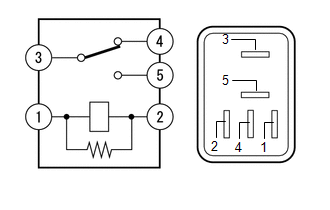
1. INSPECT NO. 1 MIRROR RELAY
(a) Remove the No. 1 mirror relay.
| (b) Measure the resistance according to the value(s) in the table below. Standard Resistance:
|
|
2. INSPECT NO. 2 MIRROR RELAY
(a) Remove the No. 2 mirror relay.
| (b) Measure the resistance according to the value(s) in the table below. Standard Resistance:
|
|
READ NEXT:
 Components
COMPONENTS ILLUSTRATION *1 DECK FLOOR BOX LH *2 NO. 3 DECK BOARD SUB-ASSEMBLY *3 REAR DECK FLOOR BOX *4 NEGATIVE AUXILIARY BATTERY TERMINAL N*m (kgf*cm, ft.*lbf): Specified
SEE MORE:
Problem Symptoms Table
PROBLEM SYMPTOMS TABLE HINT:
Use the table below to help determine the cause of problem symptoms. If multiple suspected areas are listed, the potential causes of the symptoms are listed in order of probability in the "Suspected Area" column of the table. Check each symptom by checking the suspect
Inspection
INSPECTION PROCEDURE 1. INSPECT FRONT SEAT INNER BELT ASSEMBLY LH (a) Measure the resistance according to the value(s) in the table below. *1 Connector A *2 Connector B *3 Connector C - - *a Component without harness connected (Front Seat Inner Belt Assembly LH) - -
