- Power Supply Short
Lexus NX: Power Source Control ECU Malfunction (B2782)
Lexus NX Service Manual / Steering / Steering Column / Steering Lock System / Power Source Control ECU Malfunction (B2782)
DESCRIPTION
The certification ECU (smart key ECU assembly) has a power source mode switching function.
This DTC is stored when the IGE input (the steering lock motor activation permission signal) sent directly from the certification ECU (smart key ECU assembly) to the steering lock ECU (steering lock actuator assembly) is determined to be abnormal.
HINT:
The steering lock ECU (steering lock actuator assembly) is not connected to the CAN communication system. However, the steering lock ECU (steering lock actuator assembly) is connected to the certification ECU (smart key ECU assembly) via LIN communication and communicates with other components via CAN communication through the certification ECU (smart key ECU assembly).
| DTC No. | Detection Item | DTC Detection Condition | Trouble Area | Note |
|---|---|---|---|---|
| B2782 | Power Source Control ECU Malfunction | Either of the following conditions is met (1-trip detection logic*):
HINT: If the power supply signal from the LIN communication line does not match the power supply signal from the direct line, the system is determined to be malfunctioning. |
| DTC Output Confirmation Operation: Perform a steering lock/unlock operation. (The steering locks when a door is opened with the shift lever in P and the power switch off. The steering unlocks when the power switch is turned on (ACC) or on (IG) while carrying the key.) |
- *: Only output while a malfunction is present and the power switch is on (IG).
| Vehicle Condition when Malfunction Detected | Fail-safe Function when Malfunction Detected |
|---|---|
| The steering cannot be locked or unlocked. For this reason, the hybrid control system cannot be started. | Prohibits the hybrid control system from being started (the hybrid control system does not crank). |
| DTC No. | Data List Item | Active Test Item |
|---|---|---|
| B2782 | Smart Access | - |
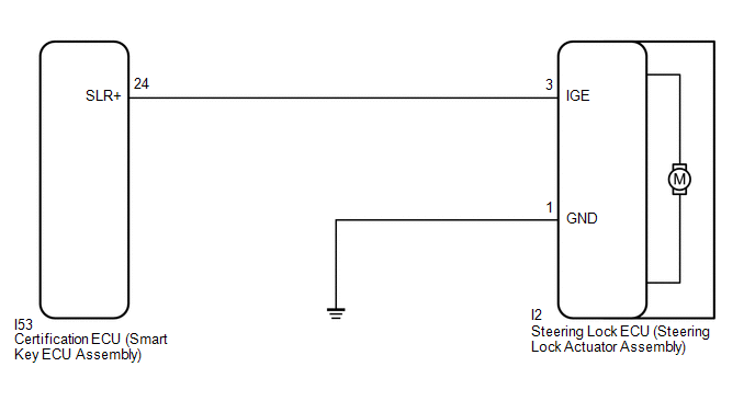
WIRING DIAGRAM
CAUTION / NOTICE / HINT
NOTICE:
- When using the Techstream with the power switch off, connect the Techstream to the vehicle and turn a courtesy light switch on and off at intervals of 1.5 seconds or less until communication between the Techstream and the vehicle begins. Then select the vehicle type under manual mode and enter the following menus: Body Electrical / Smart Access. While using the Techstream, periodically turn a courtesy light switch on and off at intervals of 1.5 seconds or less to maintain communication between the Techstream and the vehicle.
-
The steering lock system uses LIN communication. First perform the inspections in "How to Proceed with Troubleshooting" to confirm that there are no communication malfunctions before proceeding with troubleshooting.
Click here
.gif)
-
After performing repairs, perform the DTC output confirmation operation, and then confirm that no DTCs are output again.
Click here
-
When replacing the steering lock ECU (steering lock actuator assembly) or certification ECU (smart key ECU assembly), registration must be performed.
Click here
-
After the power switch is turned off, there may be a waiting time before disconnecting the negative (-) auxiliary battery terminal.
Click here
-
When disconnecting and reconnecting the auxiliary battery
Click here
HINT:
When disconnecting and reconnecting the auxiliary battery, there is an automatic learning function that completes learning when the respective system is used.
Click here
PROCEDURE
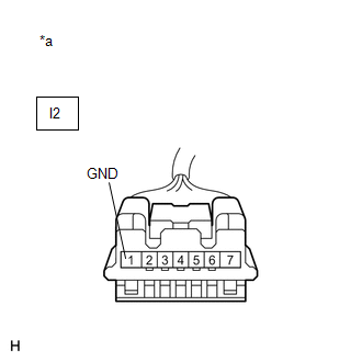
| 1. | CHECK HARNESS AND CONNECTOR (GROUND) |
(a) Disconnect the I2 steering lock ECU (steering lock actuator assembly) connector.
| (b) Measure the resistance according to the value(s) in the table below. Standard Resistance:
|
|
| NG | .gif) | REPAIR OR REPLACE HARNESS OR CONNECTOR |
|
.gif)
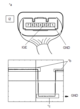
| 2. | INSPECT STEERING LOCK ECU (STEERING LOCK ACTUATOR ASSEMBLY) (MOTOR ACTIVATION COMMAND SIGNAL) |
(a) Reconnect the I2 steering lock ECU (steering lock actuator assembly) connector.
(b) Move the shift lever to P and turn the power switch off.
| (c) Check the signal waveform according to the condition(s) in the table below. Standard Frequency:
HINT:
|
|
| NG | | GO TO STEP 5 |
|
| 3. | CLEAR DTC AND DATA LIST MALFUNCTION RECORD |
(a) Clear the DTCs.
Click here
(b) Disconnect the cable from the negative (-) auxiliary battery terminal, wait for 30 seconds or more, and then reconnect the cable to the negative (-) auxiliary battery terminal to clear the record of malfunctions stored in the Data List.
NOTICE:
-
After the power switch is turned off, there may be a waiting time before disconnecting the negative (-) auxiliary battery terminal.
Click here
-
When disconnecting and reconnecting the auxiliary battery
Click here
HINT:
When disconnecting and reconnecting the auxiliary battery, there is an automatic learning function that completes learning when the respective system is used.
Click here
|
| 4. | READ VALUE USING TECHSTREAM (POWER SUPPLY SHORT) |
(a) Perform the DTC output confirmation operation.
(b) Check if DTC B2782 is output.
Click here
| Result | Proceed to |
|---|---|
| DTC B2782 is not output. | A |
| DTC B2782 is output (for Manual tilt and manual telescopic steering column). | B |
| DTC B2782 is output (for Power tilt and power telescopic steering column). | C |
| A | | SYSTEM RETURNED TO NORMAL (DTC STORED DUE TO BAD CONNECTION, BUT SYSTEM RETURNED TO NORMAL BY RECONNECTING CONNECTOR) |
| B | | REPLACE STEERING LOCK ECU (STEERING LOCK ACTUATOR ASSEMBLY) |
| C | | REPLACE STEERING LOCK ECU (STEERING LOCK ACTUATOR ASSEMBLY) |
| 5. | CHECK HARNESS AND CONNECTOR (STEERING LOCK ECU (STEERING LOCK ACTUATOR ASSEMBLY) - CERTIFICATION ECU (SMART KEY ECU ASSEMBLY)) |
(a) Make sure that there is no looseness at the locking part and the connecting part of the connectors.
(b) Disconnect the I2 steering lock ECU (steering lock actuator assembly) connector.
(c) Disconnect the I53 certification ECU (smart key ECU assembly) connector.
(d) Check for deformation and corrosion of the connector case and terminals.
OK:
There is no deformation or corrosion of the connector case or terminals.
(e) Measure the resistance according to the value(s) in the table below.
Standard Resistance:
| Tester Connection | Condition | Specified Condition |
|---|---|---|
| I2-3 (IGE) - I53-24 (SLR+) | Always | Below 1 Ω |
| I2-3 (IGE) - Body ground | Always | 10 kΩ or higher |
| I53-24 (SLR+) - Body ground | Always | 10 kΩ or higher |
| OK | | REPLACE CERTIFICATION ECU (SMART KEY ECU ASSEMBLY) |
| NG | | REPAIR OR REPLACE HARNESS OR CONNECTOR |
READ NEXT:
 IG2 Signal Malfunction (B2788)
DESCRIPTION This DTC is stored when the steering lock ECU (steering lock actuator assembly) detects an IG2 power supply malfunction. HINT: The steering lock ECU (steering lock actuator assembly) is no
Unable to Unlock Steering Wheel (Hybrid Control System cannot Start)
DESCRIPTION The steering lock actuator assembly activates the steering lock motor and moves the lock bar into the steering column to lock the steering. The steering may not unlock when the lock bar ge
Steering Lock does not Lock
DESCRIPTION The steering lock actuator assembly activates the steering lock motor and moves the lock bar into the steering column to lock the steering. When the steering lock is operating, the steerin
SEE MORE:
Telephone Main Antenna Circuit Short to Ground (B15CB11,B15CB13)
DESCRIPTION This DTC is stored when the DCM (telematics transceiver) detects an open or a short in the telephone and GPS antenna (roof antenna assembly) circuit. DTC No. Detection Item DTC Detection Condition Trouble Area B15CB11 Telephone Main Antenna Circuit Short to Ground Teleph
If your vehicle overheats
The following may indicate that
your vehicle is overheating.
The needle of the engine coolant
temperature gauge
enters the red zone, or a loss of
hybrid system power is experienced.
(For example, the vehicle
speed does not increase.)
"Engine Coolant Temp High" or
"Hybrid System Ov
© 2016-2026 Copyright www.lexunx.com
