Lexus NX: Removal
REMOVAL
CAUTION / NOTICE / HINT
HINT:
When the front bumper is damaged or deformed due to an accident or contact with other objects, etc., or the bumper installation area on the body is repaired, it is necessary to perform millimeter wave radar sensor adjustment.
Click here .gif)
PROCEDURE
1. PRECAUTION (w/ Panoramic View Monitor System)
Click here
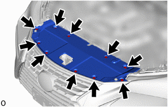
2. REMOVE RADIATOR SUPPORT OPENING COVER
| (a) Remove the 10 clips and radiator support opening cover. |
|
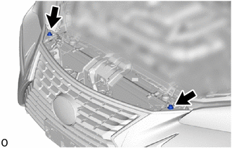
3. REMOVE RADIATOR GRILLE PROTECTOR
| (a) Remove the 2 radiator grille protectors. |
|
4. REMOVE FRONT FENDER MOULDING SUB-ASSEMBLY LH (for Front Fender)
Click here
5. REMOVE FRONT FENDER MOULDING SUB-ASSEMBLY RH (for Front Fender)
HINT:
Use the same procedure described for the LH side.
6. REMOVE NO. 1 MOULDING TAPE (for Front Fender)
Click here
7. REMOVE NO. 2 MOULDING TAPE (for Front Fender)
Click here
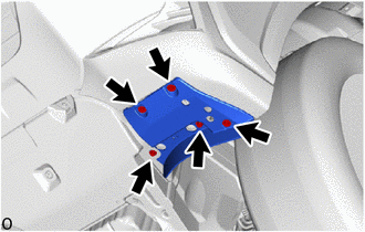
8. REMOVE FRONT FENDER FRONT SPLASH SHIELD LH
| (a) Remove the 5 screws and front fender front splash shield LH. |
|
9. REMOVE FRONT FENDER FRONT SPLASH SHIELD RH
HINT:
Use the same procedure described for the LH side.
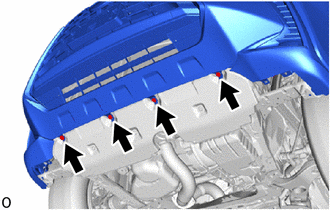
10. REMOVE FRONT BUMPER ASSEMBLY
| (a) Remove the 4 bolts. |
|
(b) Put protective tape around the front bumper assembly.
.png) | Protective Tape |
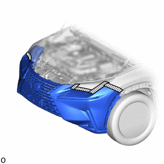
| (c) Remove the 2 clips. |
|
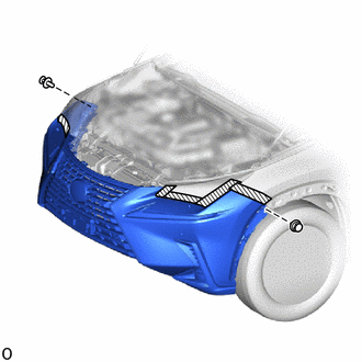
| (d) Remove the 2 bolts. |
|

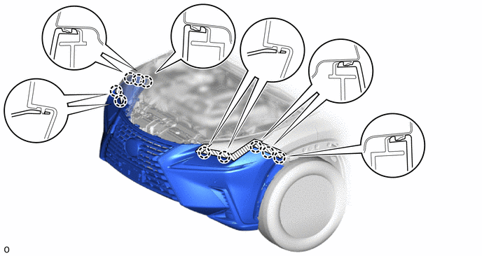
(e) Detach the 10 claws and remove the front bumper assembly.
(f) w/ Headlight Cleaner System:
(1) Disconnect the headlight washer hose, and then drain the washer fluid.
HINT:
Use a container to collect the washer fluid.
(g) Disconnect the 2 fog light connectors.
(h) Disconnect the 2 clearance light connectors.
(i) w/ Intuitive Parking Assist System:
Disconnect the 2 No. 3 engine room wire connectors.
(j) w/o Intuitive Parking Assist System:
Disconnect the No. 3 engine room wire connector.
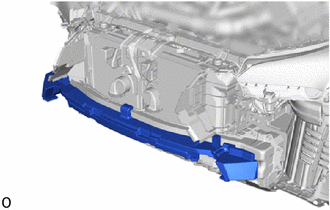
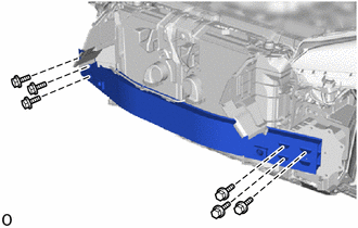
11. REMOVE FRONT BUMPER ENERGY ABSORBER
| (a) Remove the front bumper energy absorber. |
|
12. REMOVE FRONT BUMPER SIDE MOUNTING BRACKET ASSEMBLY LH
| (a) Remove the 6 bolts and front bumper side mounting bracket assembly LH. |
|
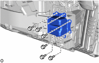
13. REMOVE FRONT BUMPER REINFORCEMENT SUB-ASSEMBLY
| (a) Remove the 6 bolts and front bumper reinforcement sub-assembly. |
|
14. REMOVE FRONT BUMPER SIDE RETAINER LH
| (a) Remove the 2 screws. |
|
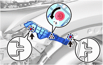
(b) Using a screwdriver, turn the clip 90° and detach the clip.
(c) Detach the 2 claws and remove the front bumper side retainer LH.
15. REMOVE FRONT BUMPER SIDE RETAINER RH
HINT:
Use the same procedure described for the LH side.
READ NEXT:
 Disassembly
DISASSEMBLY PROCEDURE 1. REMOVE HEADLIGHT WASHER ACTUATOR SUB-ASSEMBLY RH (w/ Headlight Cleaner System) Click here 2. REMOVE HEADLIGHT WASHER ACTUATOR SUB-ASSEMBLY LH (w/ Headlight Cleaner System)
Reassembly
REASSEMBLY PROCEDURE 1. INSTALL NO. 2 MOULDING TAPE HINT:
When installing the No. 2 moulding tape, heat the front bumper cover and No. 2 moulding tape using a heat light.
Use the same procedure d
Installation
INSTALLATION CAUTION / NOTICE / HINT HINT: A bolt without a torque specification is shown in the standard bolt chart. Click here PROCEDURE 1. INSTALL FRONT BUMPER SIDE RETAINER LH (a) Attach the
SEE MORE:
Installation
INSTALLATION PROCEDURE 1. INSTALL WINDSHIELD WASHER JAR ASSEMBLY (w/ Headlight Cleaner System) (a) Install the level warning switch assembly as shown in the illustration. NOTICE: Make sure that the protrusion of the level warning switch assembly is between the 2 markings. *a Protru
Trailer towing (vehicles with towing
package)
Your vehicle is designed primarily
as a passenger-and-load-carrying
vehicle. Towing a trailer can have an
adverse impact on handling, performance,
braking, durability, and
fuel consumption. For your safety
and the safety of others, you must
not overload your vehicle or trailer.
You must al
