- Stop Light Switch1
- Steering Unlock Switch
- Shift P Signal
- IG Relay Monitor (Inside)
- IG Relay Monitor (Outside)
- Latch Circuit
- Starter Request Signal
- Power Supply Condition
Lexus NX: Power Source Mode does not Change to ON (READY)
Lexus NX Service Manual / Vehicle Interior / Theft Deterrent / Keyless Entry / Smart Access System With Push-button Start (for Start Function) / Power Source Mode does not Change to ON (READY)
DESCRIPTION
When the electrical key transmitter sub-assembly is in the cabin and the power switch is pressed, the certification ECU (smart key ECU assembly) receives a signal and changes the power source mode. In addition, when the power switch is pressed with the shift lever in P and the brake pedal depressed, the hybrid control system turns on (READY).
Related Data List and Active Test Items| Problem Symptom | Data List and Active Test |
|---|---|
| Power source mode does not change to ON (READY) | Power Source Control Smart Access
|
WIRING DIAGRAM
Click here .gif)
CAUTION / NOTICE / HINT
NOTICE:
- When using the Techstream with the power switch off, connect the Techstream to the DLC3 and turn a courtesy light switch on and off at intervals of 1.5 seconds or less until communication between the Techstream and the vehicle begins. Then select the vehicle type under manual mode and enter the following menus: Body Electrical / Smart Access. While using the Techstream, periodically turn a courtesy light switch on and off at intervals of 1.5 seconds or less to maintain communication between the Techstream and the vehicle.
-
The smart access system with push-button start (for Start Function) uses the LIN communication system and CAN communication system. Inspect the communication function by following How to Proceed with Troubleshooting. Troubleshoot the smart access system with push-button start (for Start Function) after confirming that the communication systems are functioning properly.
Click here
-
If the smart access system with push-button start (for Start Function) has been canceled, enable the system before performing troubleshooting.
Click here
- Inspect the fuses of circuits related to this system before performing the following procedure.
-
Before replacing the certification ECU (smart key ECU assembly) or electrical key transmitter sub-assembly, refer to smart access system with push-button start (for Start Function) Precaution.
Click here
- After completing repairs, confirm that the problem does not recur.
HINT:
- When the cable is disconnected and reconnected to the negative (-) auxiliary battery terminal, the power source mode returns to the state it was in before the cable was disconnected.
- If the power source mode is changed from on (IG) to on (ACC) with the shift lever in any position other than P, then the shift lever is moved to P and the power switch is pressed with the brake pedal depressed, the power source mode will changed off.
PROCEDURE
| 1. | CHECK ELECTRICAL KEY TRANSMITTER SUB-ASSEMBLY |
(a) Press a switch of the electrical key transmitter sub-assembly.
OK:
The electrical key transmitter sub-assembly LED illuminates.
| NG | .gif) | GO TO STEP 11 |
|
.gif)
| 2. | READ VALUE USING TECHSTREAM (KEY LOW BATTERY) |
(a) Connect the Techstream to the DLC3.
(b) Turn the power switch on (IG).
(c) Turn the Techstream on.
(d) Enter the following menus: Body Electrical / Smart Access / Data List.
(e) Read the Data List according to the display on the Techstream.
Body Electrical > Smart Access > Data List| Tester Display | Measurement Item | Range | Normal Condition | Diagnostic Note |
|---|---|---|---|---|
| Key Low Battery | Transmitter battery depleted | No or Yes | No: Transmitter battery not depleted Yes: Transmitter battery depleted | The electrical key transmitter sub-assembly sends voltage information to the certification ECU (smart key ECU assembly) when it is transmitting. The certification ECU (smart key ECU assembly) displays "Yes" for the "Key Low Battery" item of the Data List when this voltage information indicates 2.2 V or less. This Data List item should be checked when the electrical key transmitter sub-assembly is at room temperature (example: at -20°C (-4°F), "Yes" may be displayed even if the transmitter battery is new). |
| Tester Display |
|---|
| Key Low Battery |
OK:
"No" is displayed on the Techstream screen.
| NG | | REPLACE TRANSMITTER BATTERY |
|
| 3. | CHECK WAVE ENVIRONMENT |
(a) If the problem occurs in certain locations or times of day, the possibility of wave interference is high.
HINT:
Whether the problem is due to wave interference can be checked by holding the electrical key transmitter sub-assembly near the door control receiver.
OK:
Power source mode changes to on (READY).
| OK | | AFFECTED BY WAVE INTERFERENCE |
|
| 4. | CHECK POWER SWITCH CONDITION |
(a) Get into the vehicle while carrying an electrical key transmitter sub-assembly.
(b) Move the shift lever to P.
(c) With the brake pedal released, check that pressing the power switch causes the power source mode to change.
| Result | Proceed to |
|---|---|
| Power source mode changes : Off → on (ACC) → on (IG) → off | A |
| Power source mode does not change to on (ACC) or on (IG) | B |
| Power source mode changes to on (IG) but not to on (ACC) | C |
| Power source mode changes to on (ACC) but not to on (IG) | D |
| B | | GO TO POWER SOURCE MODE DOES NOT CHANGE TO ON (IG AND ACC) |
| C | | GO TO POWER SOURCE MODE DOES NOT CHANGE TO ON (ACC) |
| D | | GO TO POWER SOURCE MODE DOES NOT CHANGE TO ON (IG) |
|
| 5. | READ VALUE USING TECHSTREAM (SHIFT P SIGNAL) |
(a) Connect the Techstream to the DLC3.
(b) Turn the power switch on (IG).
(c) Turn the Techstream on.
(d) Enter the following menus: Body Electrical / Power Source Control / Data List.
(e) Read the Data List according to the display on the Techstream.
Body Electrical > Power Source Control > Data List| Tester Display | Measurement Item | Range | Normal Condition | Diagnostic Note |
|---|---|---|---|---|
| Shift P Signal | Shift position P | OFF or ON | OFF: Shift lever not in P ON: Shift lever in P | Use this item to determine whether the shift lever position switch (P) is malfunctioning. |
| Tester Display |
|---|
| Shift P Signal |
OK:
The item in the Data List changes according to the shift position.
| NG | | GO TO HYBRID CONTROL SYSTEM (HOW TO PROCEED WITH TROUBLESHOOTING) |
|
| 6. | CHECK FOR DTC |
(a) Using the Techstream, check for DTCs.
Body Electrical > Power Source Control > Trouble Codes Body Electrical > Smart Access > Trouble Codes| Result | Proceed to |
|---|---|
| DTCs are not output | A |
| Smart access system with push-button start (for Start Function) DTCs are output | B |
| B | | GO TO DIAGNOSTIC TROUBLE CODE CHART |
|
| 7. | READ VALUE USING TECHSTREAM (STOP LIGHT SWITCH1) |
(a) Connect the Techstream to the DLC3.
(b) Turn the power switch on (IG).
(c) Turn the Techstream on.
(d) Enter the following menus: Body Electrical / Power Source Control / Data List.
(e) Read the Data List according to the display on the Techstream.
Body Electrical > Power Source Control > Data List| Tester Display | Measurement Item | Range | Normal Condition | Diagnostic Note |
|---|---|---|---|---|
| Stop Light Switch1 | State of brake pedal | OFF or ON | OFF: Brake pedal released ON: Brake pedal depressed |
|
| Tester Display |
|---|
| Stop Light Switch1 |
OK:
The Techstream display changes correctly in response to the brake operation.
| NG | | GO TO STEP 12 |
|
| 8. | READ VALUE USING TECHSTREAM (STARTER REQUEST SIGNAL) |
(a) Connect the Techstream to the DLC3.
(b) Turn the power switch on (IG).
(c) Turn the Techstream on.
(d) Enter the following menus: Body Electrical / Power Source Control / Data List.
(e) Read the Data List according to the display on the Techstream.
Body Electrical > Power Source Control > Data List| Tester Display | Measurement Item | Range | Normal Condition | Diagnostic Note |
|---|---|---|---|---|
| Starter Request Signal | Hybrid control system start request signal status | OFF or ON | OFF: After approx. 1 second has elapsed, the power switch is released ON: With the shift lever in P and brake pedal depressed, the power switch is pressed and held |
|
| Tester Display |
|---|
| Starter Request Signal |
NOTICE:
Check that the smart warning light is displayed on the multi-information display in the combination meter assembly, and then press the power switch.
OK:
The Techstream display changes correctly in response to the power switch operation.
| NG | | GO TO HYBRID CONTROL SYSTEM (HOW TO PROCEED WITH TROUBLESHOOTING) |
|
| 9. | CHECK STEERING LOCK |
(a) Check that the steering unlocks when the power switch is turned on (ACC).
OK:
The steering unlocks.
| NG | | GO TO STEERING LOCK SYSTEM (UNABLE TO UNLOCK STEERING) |
|
| 10. | CHECK SECURITY INDICATOR LIGHT (IMMOBILISER SYSTEM UNSET) |
(a) Get into the vehicle while carrying an electrical key transmitter sub-assembly.
(b) Move the shift lever to P.
(c) Press the power switch with the brake pedal released and check that the security indicator light changes from blinking to off at the same time that the power source mode changes to on (ACC).
HINT:
The immobiliser function can be determined to be operating correctly if the security indicator light changes from blinking to off at the same time that the power source mode changes to on (ACC).
OK:
The security indicator light changes from blinking to off at the same time that the power source mode changes to on (ACC).
| OK | | REPLACE CERTIFICATION ECU (SMART KEY ECU ASSEMBLY) |
| NG | | GO TO IMMOBILISER SYSTEM (PROBLEM SYMPTOMS TABLE) |
| 11. | INSPECT TRANSMITTER BATTERY |
(a) Inspect the transmitter battery.
Click here
NOTICE:
Do not wrap the lead wire around a terminal, wedge it between terminals, or solder it. The terminal may be deformed or damaged, and the transmitter battery will not be able to be installed correctly.
| OK | | REPLACE ELECTRICAL KEY TRANSMITTER SUB-ASSEMBLY |
| NG | | REPLACE TRANSMITTER BATTERY |
| 12. | CHECK HARNESS AND CONNECTOR (CERTIFICATION ECU (SMART KEY ECU ASSEMBLY) - STOP LIGHT SWITCH ASSEMBLY) |
(a) Disconnect the I51 certification ECU (smart key ECU assembly) connector.
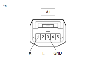
(b) Disconnect the A1 stop light switch assembly connector.
| (c) Measure the voltage according to the value(s) in the table below. Standard Voltage:
|
|
(d) Measure the resistance according to the value(s) in the table below.
Standard Resistance:
| Tester Connection | Condition | Specified Condition |
|---|---|---|
| I51-2 (STP1) - A1-2 (L) | Always | Below 1 Ω |
| I51-2 (STP1) or A1-2 (L) - Body ground | Always | 10 kΩ or higher |
| A1-3 (GND) - Body ground | Always | Below 1 Ω |
| NG | | REPAIR OR REPLACE HARNESS OR CONNECTOR |
|
| 13. | INSPECT STOP LIGHT SWITCH ASSEMBLY |
(a) Inspect the stop light switch assembly.
Click here
| OK | | REPLACE CERTIFICATION ECU (SMART KEY ECU ASSEMBLY) |
| NG | | REPLACE STOP LIGHT SWITCH ASSEMBLY |
READ NEXT:
 Precaution
PRECAUTION PRECAUTION FOR DISCONNECTING CABLE FROM NEGATIVE AUXILIARY BATTERY TERMINAL NOTICE:
After the power switch is turned off, there may be a waiting time before disconnecting the negative (-
Parts Location
PARTS LOCATION ILLUSTRATION *A w/ Security Horn Assembly *B w/o Security Horn Assembly *1 HIGH PITCHED HORN ASSEMBLY *2 LOW PITCHED HORN ASSEMBLY *3 HOOD LOCK ASSEMBLY (ENGIN
SEE MORE:
Vehicles Speed Malfunction (B2624)
DESCRIPTION The multiplex tilt and telescopic ECU forms a network with the ECUs of other systems via CAN communication. Each ECU informs the other ECUs that it is connected to the network by sending a specified signal (periodic signal) onto the communication bus on a regular basis. The multiplex til
Power Seat does not Return to Memorized Position
DESCRIPTION When either the M1, M2 or M3 switch is pressed, the outer mirror control ECU assembly (for Driver Side) sends a switch signal to the main body ECU (multiplex network body ECU) via CAN communication. Then, the main body ECU (multiplex network body ECU) sends a recall request signal to the
© 2016-2026 Copyright www.lexunx.com
