-
Communication stop for "Power Steering (EPS)" is indicated on "Communication Bus Check".
Click here
.gif)
-
Communication system DTCs (DTCs that start with U) that are output correspond to "Power Steering ECU Communication Stop Mode" in "DTC Combination Table".
Click here
Lexus NX: Power Steering ECU Communication Stop Mode
Lexus NX Service Manual / Power Source & Network / Networking / Can Communication System / Power Steering ECU Communication Stop Mode
DESCRIPTION
| Detection Item | Symptoms | Trouble Area |
|---|---|---|
| Power Steering ECU Communication Stop Mode | Any of the following conditions are met: |
|
WIRING DIAGRAM
for Power Tilt and Power Telescopic Steering Column: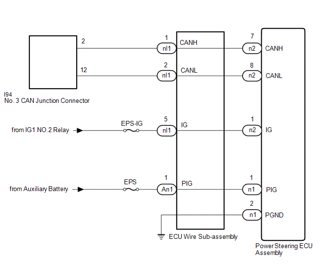 for Manual Tilt and Manual Telescopic Steering Column:
CAUTION / NOTICE / HINT
CAUTION:
When performing the confirmation driving pattern, obey all speed limits and traffic laws.
NOTICE:
- Inspect the fuses for circuits related to this system before performing the following inspection procedure.
- Before measuring the resistance of the CAN bus, turn the power switch off and leave the vehicle for 1 minute or more without operating the key, switches or opening or closing the doors. After that, disconnect the cable from the negative (-) auxiliary battery terminal and leave the vehicle for 1 minute or more before measuring the resistance.
-
After turning the power switch off, waiting time may be required before disconnecting the cable from the negative (-) auxiliary battery terminal.
Click here
-
When disconnecting and reconnecting the auxiliary battery.
Click here
HINT:
When disconnecting and reconnecting the auxiliary battery, there is an automatic learning function that completes learning when the respective system is used.
Click here
-
Some parts must be initialized and set when replacing or removing and installing parts.
Click here
-
Because the order of diagnosis is important to allow correct diagnosis, make sure to begin troubleshooting using How to Proceed with Troubleshooting when CAN communication system related DTCs are output.
Click here
-
After performing repairs, perform the DTC check procedure and confirm that the DTCs are not output again.
DTC check procedure: Turn the power switch on (IG) and wait for 1 minute or more. Then operate the suspected malfunctioning system and drive the vehicle at 60 km/h (37 mph) or more for 5 minutes or more.
-
After the repair, perform CAN Bus Check and check that all the ECUs and sensors connected to the CAN communication system are displayed as normal.
Click here
HINT:
- Operating the power switch, any switches or any doors triggers related ECU and sensor communication with the CAN, which causes resistance variation.
- Even after DTCs are cleared, if a DTC is stored again after driving the vehicle for a while, the malfunction may be occurring due to vibration of the vehicle. In such a case, wiggling the ECUs or wire harness while performing the inspection below may help determine the cause of the malfunction.
PROCEDURE
| 1. | CHECK VEHICLE TYPE |
(a) Check vehicle type.
| Result | Proceed to |
|---|---|
| for Power Tilt and Power Telescopic Steering Column | A |
| for Manual Tilt and Manual Telescopic Steering Column | B |
| B | .gif) | GO TO STEP 7 |
|
.gif)
| 2. | CHECK FOR OPEN IN CAN BUS WIRE (POWER STEERING ECU ASSEMBLY BRANCH WIRE) |
(a) Disconnect the cable from the negative (-) auxiliary battery terminal.
| (b) Disconnect the power steering ECU assembly connector. |
|
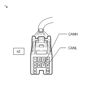
(c) Measure the resistance according to the value(s) in the table below.
Standard Resistance:
| Tester Connection | Condition | Specified Condition |
|---|---|---|
| n2-7 (CANH) - n2-8 (CANL) | Cable disconnected from negative (-) auxiliary battery terminal | 54 to 69 Ω |
| NG | | GO TO STEP 6 |
|
| 3. | CHECK HARNESS AND CONNECTOR (POWER SOURCE CIRCUIT) |
| (a) Reconnect the cable to the negative (-) auxiliary battery terminal. |
|
(b) Disconnect the ECU wire sub-assembly connector.
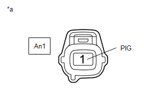
(c) Measure the voltage according to the value(s) in the table below.
Standard Voltage:
| Tester Connection | Switch Condition | Specified Condition |
|---|---|---|
| An1-1 (PIG) - Body ground | Power switch off | 9 to 16 V |
| NG | | REPAIR OR REPLACE HARNESS OR CONNECTOR (POWER SOURCE CIRCUIT) |
|
| 4. | CHECK HARNESS AND CONNECTOR (POWER SOURCE CIRCUIT) |
| (a) Disconnect the ECU wire sub-assembly connector. |
|
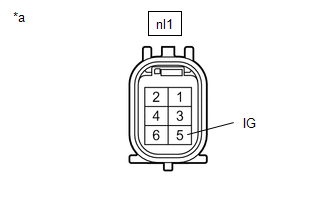
(b) Measure the voltage according to the value(s) in the table below.
Standard Voltage:
| Tester Connection | Switch Condition | Specified Condition |
|---|---|---|
| nl1-5 (IG) - Body ground | Power switch on (IG) | 11 to 14 V |
| Power switch off | Below 1 V |
| NG | | REPAIR OR REPLACE HARNESS OR CONNECTOR (POWER SOURCE CIRCUIT) |
|
| 5. | CHECK ECU WIRE SUB-ASSEMBLY |
(a) Reconnect the ECU wire sub-assembly connectors.
| (b) Disconnect the power steering ECU assembly connectors. |
|
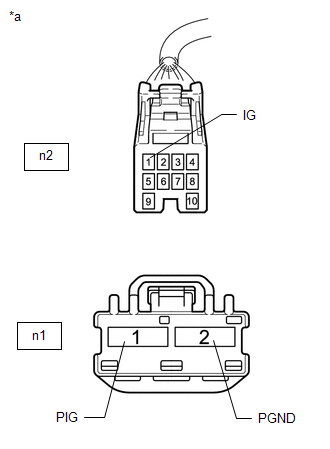
(c) Measure the voltage according to the value(s) in the table below.
Standard Voltage:
| Tester Connection | Switch Condition | Specified Condition |
|---|---|---|
| n2-1 (IG) - Body ground | Power switch on (IG) | 8 to 16 V |
| Power switch off | Below 1 V | |
| n1-1 (PIG) - Body ground | Power switch off | 9 to 16 V |
(d) Measure the resistance according to the value(s) in the table below.
Standard Resistance:
| Tester Connection | Condition | Specified Condition |
|---|---|---|
| n1-2 (PGND) - Body ground | Always | Below 1 Ω |
| OK | | REPLACE POWER STEERING ECU ASSEMBLY |
| NG | | REPLACE ECU WIRE SUB-ASSEMBLY |
| 6. | CHECK FOR OPEN IN CAN BRANCH WIRE |
| (a) Disconnect the ECU wire sub-assembly connector. |
|
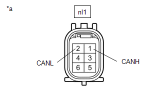
(b) Measure the resistance according to the value(s) in the table below.
Standard Resistance:
| Tester Connection | Condition | Specified Condition |
|---|---|---|
| nl1-1 (CANH) - nl1-2 (CANL) | Cable disconnected from negative (-) auxiliary battery terminal | 54 to 69 Ω |
| OK | | REPLACE ECU WIRE SUB-ASSEMBLY |
| NG | | REPAIR OR REPLACE CAN BRANCH WIRE OR CONNECTOR |
| 7. | CHECK FOR OPEN IN CAN BUS WIRE (POWER STEERING ECU ASSEMBLY BRANCH WIRE) |
(a) Disconnect the cable from the negative (-) auxiliary battery terminal.
| (b) Disconnect the power steering ECU assembly connector. |
|
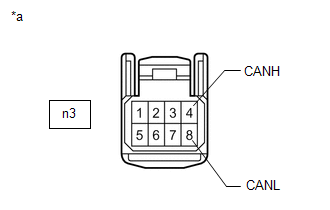
(c) Measure the resistance according to the value(s) in the table below.
Standard Resistance:
| Tester Connection | Condition | Specified Condition |
|---|---|---|
| n3-4 (CANH) - n3-8 (CANL) | Cable disconnected from negative (-) auxiliary battery terminal | 54 to 69 Ω |
| NG | | GO TO STEP 11 |
|
| 8. | CHECK HARNESS AND CONNECTOR (POWER SOURCE CIRCUIT) |
| (a) Reconnect the cable to the negative (-) auxiliary battery terminal. |
|
(b) Disconnect the ECU wire sub-assembly connector.
(c) Measure the voltage according to the value(s) in the table below.
Standard Voltage:
| Tester Connection | Switch Condition | Specified Condition |
|---|---|---|
| An1-1 (PIG) - Body ground | Power switch off | 9 to 16 V |
| NG | | REPAIR OR REPLACE HARNESS OR CONNECTOR (POWER SOURCE CIRCUIT) |
|
| 9. | CHECK HARNESS AND CONNECTOR (POWER SOURCE CIRCUIT) |
| (a) Disconnect the ECU wire sub-assembly connector. |
|
(b) Measure the voltage according to the value(s) in the table below.
Standard Voltage:
| Tester Connection | Switch Condition | Specified Condition |
|---|---|---|
| nl1-5 (IG) - Body ground | Power switch on (IG) | 11 to 14 V |
| Power switch off | Below 1 V |
| NG | | REPAIR OR REPLACE HARNESS OR CONNECTOR (POWER SOURCE CIRCUIT) |
|
| 10. | CHECK ECU WIRE SUB-ASSEMBLY |
(a) Reconnect the ECU wire sub-assembly connectors.
| (b) Disconnect the power steering ECU assembly connectors. |
|
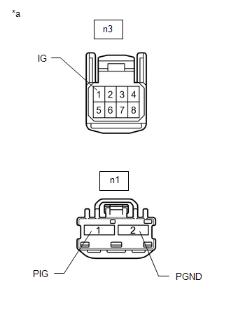
(c) Measure the voltage according to the value(s) in the table below.
Standard Voltage:
| Tester Connection | Switch Condition | Specified Condition |
|---|---|---|
| n3-1 (IG) - Body ground | Power switch on (IG) | 8 to 16 V |
| Power switch off | Below 1 V | |
| n1-1 (PIG) - Body ground | Power switch off | 9 to 16 V |
(d) Measure the resistance according to the value(s) in the table below.
Standard Resistance:
| Tester Connection | Condition | Specified Condition |
|---|---|---|
| n1-2 (PGND) - Body ground | Always | Below 1 Ω |
| OK | | REPLACE POWER STEERING ECU ASSEMBLY |
| NG | | REPLACE ECU WIRE SUB-ASSEMBLY |
| 11. | CHECK FOR OPEN IN CAN BUS WIRE (POWER STEERING ECU ASSEMBLY BRANCH WIRE) |
| (a) Disconnect the ECU wire sub-assembly connector. |
|
(b) Measure the resistance according to the value(s) in the table below.
Standard Resistance:
| Tester Connection | Condition | Specified Condition |
|---|---|---|
| nl1-1 (CANH) - nl1-2 (CANL) | Cable disconnected from negative (-) auxiliary battery terminal | 54 to 69 Ω |
| OK | | REPLACE ECU WIRE SUB-ASSEMBLY |
| NG | | REPAIR OR REPLACE CAN BRANCH WIRE OR CONNECTOR |
READ NEXT:
 Steering Angle Sensor Communication Stop Mode
DESCRIPTION Detection Item Symptom Trouble Area Steering Angle Sensor Communication Stop Mode Any of the following conditions are met:
Communication stop for "Spiral cable (Steering An
ECM Communication Stop Mode
DESCRIPTION Detection Item Symptom Trouble Area ECM Communication Stop Mode Any of the following conditions are met:
Communication stop for "Engine" is indicated on the "Communication
Main Body ECU Communication Stop Mode
DESCRIPTION Detection Item Symptom Trouble Area Main Body ECU Communication Stop Mode Any of the following conditions are met:
Communication stop for "Main Body" is indicated on the "C
SEE MORE:
Hybrid System Indicator Malfunction
DESCRIPTION A hybrid system indicator has been used on this vehicle. In this circuit, the combination meter assembly receives the eco-zone indicator level signal from the hybrid vehicle control ECU via CAN communication. The combination meter assembly controls the operation of the hybrid system indi
Evaporator Temperature Circuit or Evaporator Fin Thermistor (B1413)
DESCRIPTION The No. 1 cooler thermistor (evaporator temperature sensor) is installed on the evaporator in the air conditioner unit to detect the temperature of the air that has passed through the evaporator and is used to control the air conditioning. It sends signals to the air conditioning amplifi
© 2016-2026 Copyright www.lexunx.com
