Lexus NX: Door Unlock Detection Switch Circuit
DESCRIPTION
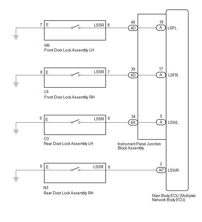
The main body ECU (multiplex network body ECU) detects the condition of each door unlock detection switch.
WIRING DIAGRAM
CAUTION / NOTICE / HINT
NOTICE:
- Recognition code registration is necessary when replacing the main body ECU (multiplex network body ECU).
- If the main body ECU (multiplex network body ECU) is replaced, refer to Registration.
PROCEDURE
| 1. | READ VALUE USING TECHSTREAM (DOOR LOCK POS) |
(a) Using the Techstream, read the Data List.
Click here .gif)
| Tester Display | Measurement Item | Range | Normal Condition | Diagnostic Note |
|---|---|---|---|---|
| FR Door Lock Pos | Front door unlock detection switch RH signal | UNLOCK or LOCK | UNLOCK: Front door RH unlocked LOCK: Front door RH locked | - |
| FL Door Lock Pos | Front door unlock detection switch LH signal | UNLOCK or LOCK | UNLOCK: Front door LH unlocked LOCK: Front door LH locked | - |
| RR-Door Lock Pos SW | Rear door unlock detection switch RH signal | ON or OFF | ON: Rear door RH unlocked OFF: Rear door RH locked | - |
| RL-Door Lock Pos SW | Rear door unlock detection switch LH signal | ON or OFF | ON: Rear door LH unlocked OFF: Rear door LH locked | - |
| Tester Display |
|---|
| FR Door Lock Pos |
| FL Door Lock Pos |
| RR-Door Lock Pos SW |
| RL-Door Lock Pos SW |
OK:
The display is as specified in the normal condition column.
| Result | Proceed to |
|---|---|
| OK | A |
| NG (Front door unlock detection switch RH does not operate) | B |
| NG (Front door unlock detection switch LH does not operate) | C |
| NG (Rear door unlock detection switch RH does not operate) | D |
| NG (Rear door unlock detection switch LH does not operate) | E |
| A | .gif) | PROCEED TO NEXT SUSPECTED AREA SHOWN IN PROBLEM SYMPTOMS TABLE |
| C | | GO TO STEP 5 |
| D | | GO TO STEP 8 |
| E | | GO TO STEP 10 |
|
.gif)
| 2. | INSPECT FRONT DOOR LOCK ASSEMBLY RH |
(a) Remove the front door lock assembly RH.
Click here
(b) Inspect the front door lock assembly RH.
Click here
| NG | | REPLACE FRONT DOOR LOCK ASSEMBLY RH |
|
| 3. | CHECK HARNESS AND CONNECTOR (FRONT DOOR LOCK ASSEMBLY RH - INSTRUMENT PANEL JUNCTION BLOCK ASSEMBLY AND BODY GROUND) |
(a) Disconnect the 4D instrument panel junction block assembly connector.
(b) Disconnect the L6 front door lock assembly RH connector.
(c) Measure the resistance according to the value(s) in the table below.
Standard Resistance:
| Tester Connection | Condition | Specified Condition |
|---|---|---|
| L6-7 (LSSR) - 4D-39 | Always | Below 1 Ω |
| L6-8 (E) - Body ground | Always | Below 1 Ω |
| L6-7 (LSSR) or 4D-39 - Body ground | Always | 10 kΩ or higher |
| NG | | REPAIR OR REPLACE HARNESS OR CONNECTOR |
|
| 4. | INSPECT INSTRUMENT PANEL JUNCTION BLOCK ASSEMBLY |
| (a) Remove the instrument panel junction block assembly. Click here |
|
(b) Remove the main body ECU (multiplex network body ECU) from the instrument panel junction block assembly.
Click here
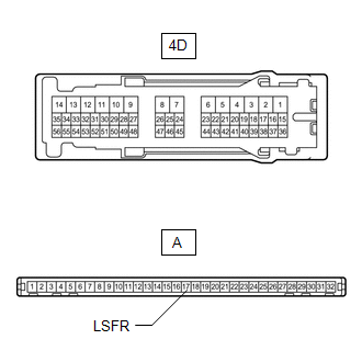
(c) Measure the resistance according to the value(s) in the table below.
Standard Resistance:
| Tester Connection | Condition | Specified Condition |
|---|---|---|
| A-17 (LSFR) - 4D-39 | Always | Below 1 Ω |
| OK | | REPLACE MAIN BODY ECU (MULTIPLEX NETWORK BODY ECU) |
| NG | | REPLACE INSTRUMENT PANEL JUNCTION BLOCK ASSEMBLY |
| 5. | INSPECT FRONT DOOR LOCK ASSEMBLY LH |
(a) Remove the front door lock assembly LH.
Click here
(b) Inspect the front door lock assembly LH.
Click here
| NG | | REPLACE FRONT DOOR LOCK ASSEMBLY LH |
|
| 6. | CHECK HARNESS AND CONNECTOR (FRONT DOOR LOCK ASSEMBLY LH - INSTRUMENT PANEL JUNCTION BLOCK ASSEMBLY AND BODY GROUND) |
(a) Disconnect the 4D instrument panel junction block assembly connector.
(b) Disconnect the M6 front door lock assembly RH connector.
(c) Measure the resistance according to the value(s) in the table below.
Standard Resistance:
| Tester Connection | Condition | Specified Condition |
|---|---|---|
| M6-8 (LSSR) - 4D-40 | Always | Below 1 Ω |
| M6-7 (E) - Body ground | Always | Below 1 Ω |
| M6-8 (LSSR) or 4D-40 - Body ground | Always | 10 kΩ or higher |
| NG | | REPAIR OR REPLACE HARNESS OR CONNECTOR |
|
| 7. | INSPECT INSTRUMENT PANEL JUNCTION BLOCK ASSEMBLY |
| (a) Remove the instrument panel junction block assembly. Click here |
|
(b) Remove the main body ECU (multiplex network body ECU) from the instrument panel junction block assembly.
Click here
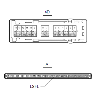
(c) Measure the resistance according to the value(s) in the table below.
Standard Resistance:
| Tester Connection | Condition | Specified Condition |
|---|---|---|
| A-19 (LSFL) - 4D-40 | Always | Below 1 Ω |
| OK | | REPLACE MAIN BODY ECU (MULTIPLEX NETWORK BODY ECU) |
| NG | | REPLACE INSTRUMENT PANEL JUNCTION BLOCK ASSEMBLY |
| 8. | INSPECT REAR DOOR LOCK ASSEMBLY RH |
(a) Remove the rear door lock assembly RH.
Click here
(b) Inspect the rear door lock assembly RH.
Click here
| NG | | REPLACE REAR DOOR LOCK ASSEMBLY RH |
|
| 9. | CHECK HARNESS AND CONNECTOR (REAR DOOR LOCK ASSEMBLY RH - MAIN BODY ECU AND BODY GROUND) |
(a) Disconnect the N3 rear door with motor lock assembly RH connector.
(b) Disconnect the I47 main body ECU (multiplex network body ECU) connector.
(c) Measure the resistance according to the value(s) in the table below.
Standard Resistance:
| Tester Connection | Condition | Specified Condition |
|---|---|---|
| N3-6 (LSSR) - I47-2 (LSWR) | Always | Below 1 Ω |
| N3-9 (E) - Body ground | Always | Below 1 Ω |
| N3-6 (LSSR) or I47-2 (LSWR) - Body ground | Always | 10 kΩ or higher |
| OK | | REPLACE MAIN BODY ECU (MULTIPLEX NETWORK BODY ECU) |
| NG | | REPAIR OR REPLACE HARNESS OR CONNECTOR |
| 10. | INSPECT REAR DOOR LOCK ASSEMBLY LH |
(a) Remove the rear door lock assembly LH.
Click here
(b) Inspect the rear door lock assembly LH.
Click here
| NG | | REPLACE REAR DOOR LOCK ASSEMBLY LH |
|
| 11. | CHECK HARNESS AND CONNECTOR (REAR DOOR LOCK ASSEMBLY LH - INSTRUMENT PANEL JUNCTION BLOCK ASSEMBLY AND BODY GROUND) |
(a) Disconnect the 4A instrument panel junction block assembly connector.
(b) Disconnect the O3 rear door lock assembly LH connector.
(c) Measure the resistance according to the value(s) in the table below.
Standard Resistance:
| Tester Connection | Condition | Specified Condition |
|---|---|---|
| O3-6 (LSSR) - 4A-34 | Always | Below 1 Ω |
| O3-9 (E) - Body ground | Always | Below 1 Ω |
| O3-6 (LSSR) or 4A-34 - Body ground | Always | 10 kΩ or higher |
| NG | | REPAIR OR REPLACE HARNESS OR CONNECTOR |
|
| 12. | INSPECT INSTRUMENT PANEL JUNCTION BLOCK ASSEMBLY |
| (a) Remove the instrument panel junction block assembly. Click here |
|
(b) Remove the main body ECU (multiplex network body ECU) from the instrument panel junction block assembly.
Click here
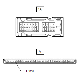
(c) Measure the resistance according to the value(s) in the table below.
Standard Resistance:
| Tester Connection | Condition | Specified Condition |
|---|---|---|
| A-5 (LSWL) - 4A-34 | Always | Below 1 Ω |
| OK | | REPLACE MAIN BODY ECU (MULTIPLEX NETWORK BODY ECU) |
| NG | | REPLACE INSTRUMENT PANEL JUNCTION BLOCK ASSEMBLY |
READ NEXT:
 Luggage Compartment Room Light
ComponentsCOMPONENTS ILLUSTRATION *1 NO. 1 LUGGAGE COMPARTMENT LIGHT ASSEMBLY - - RemovalREMOVAL PROCEDURE 1. REMOVE NO. 1 LUGGAGE COMPARTMENT LIGHT ASSEMBLY (for LH Side) (a) Put prote
Components
COMPONENTS ILLUSTRATION *1 MAP LIGHT ASSEMBLY (PERSONAL LIGHT) *2 MAP LIGHT SUB-ASSEMBLY
SEE MORE:
Disassembly
DISASSEMBLY PROCEDURE 1. REMOVE AIR FILTER CASE (a) Detach the claw and guide and remove the air filter case. 2. REMOVE AIR REFINER ELEMENT (a) Remove the air refiner element. 3. REMOVE BLOWER WITH FAN MOTOR SUB-ASSEMBLY (a) Remove the 3 screws and the blower with fa
Driver Side Camera Video Sync Signal Malfunction (C1686)
DESCRIPTION This DTC is stored if the parking assist ECU judges as a result of its self check that a synchronization problem is occurring in the image signal sent from the driver side television camera assembly to the parking assist ECU. DTC No. Detection Item DTC Detection Condition Troubl
