Lexus NX: Pre-collision System Warning Buzzer
Components
COMPONENTS
ILLUSTRATION
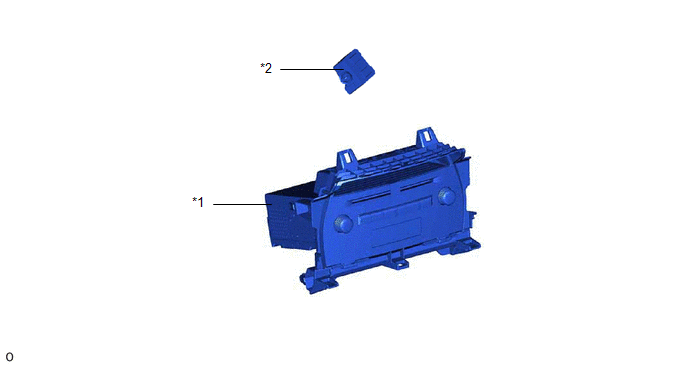
| *1 | RADIO RECEIVER ASSEMBLY | *2 | SKID CONTROL BUZZER ASSEMBLY (PRE-COLLISION SYSTEM WARNING BUZZER) |
Inspection
INSPECTION
PROCEDURE
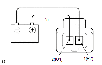
1. INSPECT SKID CONTROL BUZZER ASSEMBLY (PRE-COLLISION SYSTEM WARNING BUZZER)
| (a) Apply battery voltage and check the operation of the skid control buzzer assembly (pre-collision system warning buzzer) according to the table below. OK:
If the result is not as specified, replace the skid control buzzer assembly (pre-collision system warning buzzer). |
|
Removal
REMOVAL
PROCEDURE
1. REMOVE RADIO RECEIVER ASSEMBLY
Click here .gif)
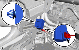
2. REMOVE SKID CONTROL BUZZER ASSEMBLY (PRE-COLLISION SYSTEM WARNING BUZZER)
(a) Using a clip remover, disconnect the clamp.
| (b) Disconnect the connector and remove the skid control buzzer assembly (pre-collision system warning buzzer). |
|
Installation
INSTALLATION
PROCEDURE
1. INSTALL SKID CONTROL BUZZER ASSEMBLY (PRE-COLLISION SYSTEM WARNING BUZZER)
(a) Connect the connector.
(b) Install the skid control buzzer assembly (pre-collision system warning buzzer) with the clamp.
2. INSTALL RADIO RECEIVER ASSEMBLY
Click here .gif)
READ NEXT:
 Precaution
PRECAUTION FOR OPERATION OF ELECTRICAL ITEMS RESTRICTED NOTICE:
If the auxiliary battery voltage is low, the climate control seat system may not operate. When "High Power Consumption / Partial Limi
SEE MORE:
Installation
INSTALLATION PROCEDURE 1. INSTALL REAR HEADER SPEAKER ASSEMBLY NOTICE: Do not touch the cone part of the speaker. (a) Temporarily install the speaker by attaching the clip of the speaker to the vehicles body. (b) Install the rear header speaker assembly with the bolt. Torque: 7.5 N·
Components
COMPONENTS ILLUSTRATION *A for Manual Seat *B for Power Seat *1 NO. 2 BATTERY SERVICE COVER BOARD *2 NO. 3 BATTERY SERVICE COVER BOARD *3 REAR DOOR SCUFF PLATE LH *4 REAR DOOR SCUFF PLATE RH *5 REAR SEAT CUSHION ASSEMBLY *6 RECLINING ADJUSTER RELEASE HANDLE LH
