- The main body ECU (multiplex network body ECU) functions as a gateway between the bus 2 and sub bus 1
- Connected to LIN communication system
Lexus NX: System Diagram
Lexus NX Service Manual / Power Source & Network / Networking / Can Communication System / System Diagram
SYSTEM DIAGRAM
SYSTEM DIAGRAM
(a) The CAN communication system is composed of 5 buses.
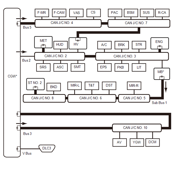
 | CAN Main Bus Line |  | Terminating Resistor |
 | CAN Branch Line | * | Gateway Function Equipped ECU |
 | Bus Monitoring Direction | - | - |
| Connected to | Code | ECU/Sensor Name | CAN DTC Storage | Note |
|---|---|---|---|---|
| - | CGW | Central Gateway ECU (Network Gateway ECU) | - | - |
| V Bus | DLC3 | DLC3 | - | - |
| Bus 2 | MET | Combination Meter Assembly | Available | - |
| STR | Steering Sensor | - | - | |
| EPS | Power Steering ECU Assembly | Available | - | |
| SMT | Certification ECU (Smart Key ECU Assembly) | Available | - | |
| SRS | Airbag ECU Assembly | - | - | |
| A/C | Air Conditioning Amplifier Assembly | Available | - | |
| MB | Main Body ECU (Multiplex Network Body ECU) | Available | | |
| HUD | Meter Mirror Sub-assembly | Available | w/ Headup Display | |
| BRK | Brake Booster with Master Cylinder Assembly (Skid Control ECU) | Available | - | |
| PKB | Parking Brake ECU Assembly | Available | - | |
| ASC | Stereo Component Equalizer Assembly | Available | w/ ASC System | |
| LIT | Headlight ECU Sub-assembly LH | Available | for Triple Beam Headlight | |
| ENG | ECM | Available | - | |
| HV | Hybrid Vehicle Control ECU | Available | - | |
| CAN J/C NO. 2 | No. 2 CAN Junction Connector | - | - | |
| CAN J/C NO. 3 | No. 3 CAN Junction Connector | - | - | |
| Bus 3 | YGW | Bus Buffer ECU | - | w/ Bus Buffer ECU |
| DCM | DCM (Telematics Transceiver) | Available | w/ Telematics Transceiver | |
| AV | Radio Receiver Assembly | Available | - | |
| CAN J/C NO. 10 | No. 10 CAN Junction Connector | - | - | |
| Bus 5 | F-MR | Millimeter Wave Radar Sensor Assembly | Available | w/ Pre-collision System |
| F-CAM | Forward Recognition Camera | Available | w/ Pre-collision System | |
| VAS | Vehicle Approaching Speaker Controller | Available | - | |
| CS | Clearance Warning ECU Assembly | Available | w/ Intuitive Parking Assist System | |
| PAC | Parking Assist ECU | Available | w/ Panoramic View Monitor System | |
| BSM | Blind Spot Monitor Sensor LH | Available | w/ Blind Spot Monitor System | |
| SUS | Absorber Control ECU | Available | w/ Adaptive Variable Suspension System | |
| R-CA | Rear Television Camera Assembly | Available | - | |
| HV | Hybrid Vehicle Control ECU | Available | - | |
| CAN J/C NO. 4 | No. 4 CAN Junction Connector | - | - | |
| CAN J/C NO. 7 | No. 7 CAN Junction Connector | - | - | |
| Sub Bus 1 | MB | Main Body ECU (Multiplex Network Body ECU) | Available |
|
| T&T | Multiplex Tilt and Telescopic ECU | Available | for Power Tilt and Power Telescopic Steering Column | |
| DST | Front Power Seat Switch (for Driver Side) | - | w/ Memory | |
| MIR-R | Outer Mirror Control ECU Assembly RH | Available | w/ Memory | |
| MIR-L | Outer Mirror Control ECU Assembly LH | Available | w/ Memory | |
| BKD | Multiplex Network Door ECU | Available | w/ Power Back Door System | |
| ST NO. 2 | No. 2 CAN Junction Terminal | - | - | |
| CAN J/C NO. 5 | No. 5 CAN Junction Connector | - | - | |
| CAN J/C NO. 6 | No. 6 CAN Junction Connector | - | - | |
| CAN J/C NO. 8 | No. 8 CAN Junction Connector | - | - |
READ NEXT:
 System Description
SYSTEM DESCRIPTION BRIEF DESCRIPTION (a) The Controller Area Network (CAN) is a serial data communication system for real time application. It is a vehicle multiplex communication system which has a h
How To Proceed With Troubleshooting
CAUTION / NOTICE / HINT PRECAUTIONS WHEN TROUBLESHOOTING NOTICE:
Because the order of diagnosis is important to allow correct diagnosis, make sure to begin troubleshooting using How to Proceed with
Utility
UTILITY INITIALIZE THE CONNECTION INFORMATION OF A GATEWAY FUNCTION EQUIPPED ECU (BUS MONITOR ECU) (a) Connect the Techstream to the DLC3. (b) Turn the power switch on (IG). (c) Turn the Techstream on
SEE MORE:
Dtc Check / Clear
DTC CHECK / CLEAR CHECK DTC (a) Connect the Techstream to the DLC3. (b) Turn the power switch on (IG). (c) Turn the Techstream on. (d) Enter the following menus: Body Electrical / Main Body / Trouble Codes. Body Electrical > Main Body > Trouble Codes (e) Check for DTCs. CLEAR DTC (a) Connect t
Motor Drive Permission Malfunction (C1451)
DESCRIPTION If air bleeding has not been performed, the skid control ECU (brake booster with master cylinder assembly) stores DTC C1451 to prevent the entry of air due to pump motor operation. DTC C1451 is stored when Invalid Mode is selected, the system will not return to normal until the air bleed
© 2016-2026 Copyright www.lexunx.com
