Lexus NX: On-vehicle Inspection
ON-VEHICLE INSPECTION
PROCEDURE
1. INSPECT COOLING FAN MOTOR
(a) Disconnect the cooling fan motor connector.
(b) Check that the fan rotates smoothly by hand.
| (c) Check that the cooling fan motor turns smoothly when the battery is connected to the cooling fan motor connector. Click here |
|
.gif)
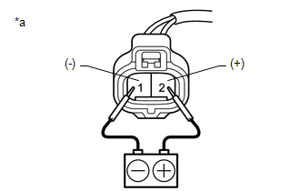
(d) Measure the current according to the value(s) in the table below.
Standard Current:
| Tester Connection | Condition | Specified Condition |
|---|---|---|
| 2 (+) | 20°C (68°F) 12 V | 14.1 to 18.1 A |
If the result is not as specified, replace the cooling fan motor.
(e) Connect the cooling fan motor connector.
2. INSPECT NO. 2 COOLING FAN MOTOR
(a) Disconnect the No. 2 cooling fan motor connector.
(b) Check that the No. 2 fan rotates smoothly by hand.
| (c) Check that the No. 2 cooling fan motor turns smoothly when the battery is connected to the No. 2 cooling fan motor connector. Click here |
|
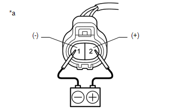
(d) Measure the current according to the value(s) in the table below.
Standard Current:
| Tester Connection | Condition | Specified Condition |
|---|---|---|
| 2 (+) | 20°C (68°F) 12 V | 14.1 to 18.1 A |
If the result is not as specified, replace the No. 2 cooling fan motor.
(e) Connect the No. 2 cooling fan motor connector.
READ NEXT:
 Removal
REMOVAL PROCEDURE 1. REMOVE FAN SHROUD WITH COOLING FAN Click here 2. REMOVE COOLING FAN WIRE (a) Disconnect the cooling fan ECU connector. (b) Detach the 3 clamps and remove the cool
Installation
INSTALLATION PROCEDURE 1. INSTALL NO. 2 COOLING FAN MOTOR (a) Attach the 2 clamps and install the No. 2 cooling fan motor with the 3 screws. Torque: 3.9 N·m {40 kgf·cm, 35 in·lbf} (b) Install the
SEE MORE:
Door Unlock Detection Switch Circuit
DESCRIPTION The main body ECU (multiplex network body ECU) detects the condition of each door unlock detection switch. WIRING DIAGRAM CAUTION / NOTICE / HINT NOTICE:
Recognition code registration is necessary when replacing the main body ECU (multiplex network body ECU).
If the main body ECU (
Installation
INSTALLATION PROCEDURE 1. INSTALL FRONT LUMBAR POWER SEAT SWITCH (a) Attach the 4 claws to install the front lumbar power seat switch. 2. INSTALL FRONT POWER SEAT SWITCH LH Click here 3. INSTALL FRONT SEAT CUSHION SHIELD LH Click here 4. INSTALL POWER SEAT SWITCH KNOB LH Click here 5. INSTALL
