Lexus NX: Rear Door Opening Trim Weatherstrip
Components
COMPONENTS
ILLUSTRATION
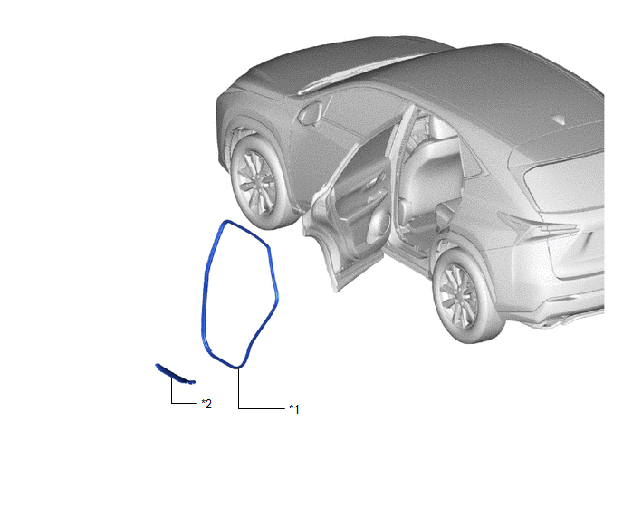
| *1 | REAR DOOR OPENING TRIM WEATHERSTRIP LH | *2 | REAR DOOR SCUFF PLATE LH |
Removal
REMOVAL
CAUTION / NOTICE / HINT
HINT:
- Use the same procedure for the RH and LH side.
- The procedure listed below is for the LH side.
PROCEDURE
1. REMOVE REAR DOOR SCUFF PLATE LH
Click here .gif)
2. REMOVE REAR DOOR OPENING TRIM WEATHERSTRIP LH
| (a) Remove the rear door opening trim weatherstrip LH. |
|
Installation
INSTALLATION
CAUTION / NOTICE / HINT
HINT:
- Use the same procedure for RHD and LHD vehicles.
- The procedure listed below is for LHD vehicles.
- Use the same procedure for the RH and LH sides.
- The procedure listed below is for the LH side.
PROCEDURE
1. INSTALL REAR DOOR OPENING TRIM WEATHERSTRIP LH
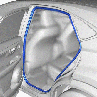
| (a) Align the paint mark on the rear door opening trim weatherstrip LH with the mark position on the vehicle and install the rear door opening trim weatherstrip LH as shown in the illustration. |
|

2. INSTALL REAR DOOR SCUFF PLATE LH
Click here .gif)
READ NEXT:
 Relay
Relay
InspectionINSPECTION PROCEDURE 1. INSTALL RELAY BLOCK ASSEMBLY (a) Preparations for inspection (1) Connect the positive battery terminal to terminal 2 of the fuel lid opener relay and the negative
Reserve Lock Switch
ComponentsCOMPONENTS ILLUSTRATION *1 DOOR CONTROL SWITCH *2 PULL HANDLE RemovalREMOVAL PROCEDURE 1. REMOVE PULL HANDLE Click here 2. REMOVE DOOR CONTROL SWITCH (a) Detach the 2 cla
SEE MORE:
Problem Symptoms Table
PROBLEM SYMPTOMS TABLE HINT:
Use the table below to help determine the cause of problem symptoms. If multiple suspected areas are listed, the potential causes of the symptoms are listed in order of probability in the "Suspected Area" column of the table. Check each symptom by checking the suspect
HD Radio Tuner Malfunction (B1551,B15A0,B15B3,B15B5,B15B7,B15BA,B15F9)
DESCRIPTION These DTCs are stored when a malfunction occurs in the radio receiver assembly DTC No. Detection Item DTC Detection Condition Trouble Area B1551 HD Radio Tuner Malfunction When one of the conditions below is met:
"HD Radio" tuner decoder malfunction
"HD Radio" tuner
© 2016-2026 Copyright www.lexunx.com
