
Lexus NX: Relay
Inspection
INSPECTION
PROCEDURE
1. INSTALL RELAY BLOCK ASSEMBLY
| (a) Preparations for inspection (1) Connect the positive battery terminal to terminal 2 of the fuel lid opener relay and the negative battery terminal to terminal 1. |
|
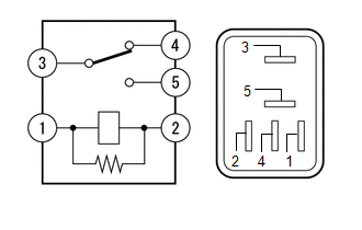
(b) Measure resistance
(1) Measure the resistance according to the value(s) in the table below.
Standard Resistance:
| Tester Connection | Condition | Specified Condition |
|---|---|---|
| 4 - 3 | Battery not connected | Below 1 Ω |
| Battery connected | 10 kΩ or higher | |
| 5 - 3 | Battery not connected | |
| Battery connected | Below 1 Ω |
READ NEXT:
 Reserve Lock Switch
ComponentsCOMPONENTS ILLUSTRATION *1 DOOR CONTROL SWITCH *2 PULL HANDLE RemovalREMOVAL PROCEDURE 1. REMOVE PULL HANDLE Click here 2. REMOVE DOOR CONTROL SWITCH (a) Detach the 2 cla
SEE MORE:
Power Window Master Switch
ComponentsCOMPONENTS ILLUSTRATION *1 MULTIPLEX NETWORK MASTER SWITCH ASSEMBLY *2 POWER WINDOW REGULATOR MASTER SWITCH ASSEMBLY WITH FRONT DOOR ARMREST BASE PANEL *3 FRONT DOOR ARMREST BASE PANEL - - RemovalREMOVAL PROCEDURE 1. REMOVE POWER WINDOW REGULATOR MASTER SWITCH ASSE
Drive Motor "A" Inverter Performance (P0A78-279)
DTC SUMMARY MALFUNCTION DESCRIPTION These DTCs indicate that an overvoltage in the inverter has occurred. The cause of this malfunction may be one of the following: Internal inverter malfunction
Inverter internal circuit malfunction
Malfunction in the sensors for inverter control (current senso
© 2016-2026 Copyright www.lexunx.com
